Uncategorized

vapor chamber production equipment

Vapor Chamber Degassing Machine: Process and Benefits

Vapor Chamber Degassing Machine: Process and Benefits 1. What Is a Vapor Chamber Degassing Machine? A Vapor Chamber Degassing Machine is specialized manufacturing equipment used to remove unwanted gases and volatile residues from vapor chamber assemblies or their internal working environment. Depending on the production process, degassing may take place before working-fluid filling, during vacuum processing, or as part of a combined evacuation and sealing operation. A vapor chamber is a two-phase heat transfer device. It contains a sealed enclosure, a working fluid, and an internal wick structure. During operation, the working fluid evaporates near a heat source and condenses in a cooler region. This cycle distributes heat across the chamber. However, non-condensable gases can interfere with this process. They may occupy part of the internal vapor space and reduce the effective area available for condensation. Consequently, poor gas removal can contribute to inconsistent thermal performance. A vapor chamber degassing machine helps manufacturers control this important production stage. Depending on its design, the equipment may use a vacuum system, controlled heating, process fixtures, and monitoring instruments to remove residual gases. The exact configuration depends on the chamber structure, materials, working fluid, and manufacturing sequence. Some systems perform degassing as a standalone operation. Others integrate it with vacuum filling, liquid charging, and sealing equipment. For manufacturers, the objective is straightforward: establish a repeatable process that supports internal cleanliness, controlled evacuation, and consistent product quality. 2. Why Degassing Matters in Vapor Chamber Manufacturing Degassing is not simply an additional manufacturing step. It supports the preparation of the internal environment required for reliable two-phase heat transfer. 2.1 Removing Non-Condensable Gases Non-condensable gases do not participate in the normal evaporation and condensation cycle of the working fluid. Instead, they can accumulate in parts of the vapor chamber and obstruct vapor movement or condensation. As a result, the chamber may not use its available condensation area effectively. The severity depends on the amount of residual gas, its distribution, and the chamber’s operating conditions. A controlled degassing process helps reduce this risk. However, its effectiveness also depends on leak prevention, material cleanliness, and subsequent sealing quality. 2.2 Supporting Consistent Vacuum Conditions Many vapor chamber manufacturing processes require evacuation before working-fluid charging and final sealing. The target vacuum depends on the product design and process specification. A suitable degassing machine helps manufacturers reach and maintain the required process conditions. It can also support repeatable evacuation cycles across production batches. Nevertheless, reaching a low pressure reading does not automatically prove that every internal surface is free from contamination or that the finished chamber is leak-tight. 2.3 Reducing Residual Contamination Moisture, trapped air, and volatile residues may remain after forming, cleaning, assembly, or handling. Their presence can affect the internal environment. Depending on the process, controlled heating under vacuum may help release moisture or volatile substances. Manufacturers must select compatible temperatures and cycle times to avoid damaging the chamber, wick structure, joints, or other components. Degassing should therefore work alongside effective cleaning and drying procedures. It cannot compensate for every contamination problem. 2.4 Improving Process Repeatability Manual vacuum processing can introduce variations in handling, timing, temperature, and pressure control. A properly configured Vapor Chamber Degassing Machine can standardize key process steps. Automated recipes may help operators repeat established settings and identify deviations. This repeatability is particularly valuable when manufacturers produce multiple chamber sizes or run frequent production batches. 3. How a Vapor Chamber Degassing Machine Works A vapor chamber degassing machine generally creates controlled conditions that encourage unwanted gases and certain volatile substances to leave the assembly. The precise mechanism depends on whether the system processes an empty chamber, an assembled chamber, or a component before fluid charging. 3.1 Loading and Fixture Positioning Operators place the workpieces into a designated fixture or vacuum chamber. The fixture keeps the parts stable and provides suitable access for evacuation. Fixture design matters because trapped pockets, blocked openings, or poorly arranged parts can slow gas removal. For production equipment, manufacturers should consider loading convenience, chamber size, and compatibility with different product dimensions. 3.2 Vacuum Evacuation The machine closes its vacuum chamber and starts the evacuation sequence. A vacuum pump removes gas from the processing space. As pressure decreases, gas can escape from accessible internal spaces through the available flow paths. However, complex wick structures, narrow channels, and trapped volumes may require carefully designed process conditions. The pressure reached by the system depends on the vacuum pump, chamber leakage, outgassing load, piping, valves, and workpiece configuration. 3.3 Controlled Heating When Required Some degassing processes use controlled heating to accelerate the release of moisture or volatile substances. Heating can increase the rate at which certain contaminants leave surfaces and materials. However, temperature must remain compatible with the workpiece and the process sequence. Excessive heating may damage coatings, seals, fixtures, or internal components. Therefore, temperature selection should follow product-specific validation rather than a universal setting. 3.4 Holding and Monitoring The equipment maintains the specified conditions for a defined period. During this stage, the control system may monitor pressure, temperature, and elapsed time. A pressure trend can help operators understand whether the chamber is approaching a stable condition. A rising pressure may indicate continued outgassing, leakage, or other process issues. Pressure behavior alone cannot identify every root cause. Additional checks may be needed when a cycle fails to meet its acceptance criteria. 3.5 Completing the Cycle Once the process reaches its specified endpoint, the system follows the programmed sequence. Depending on the machine design, this may include controlled cooling, isolation, venting, or transfer to the next operation. If the degassing step precedes working-fluid filling, the workpiece may move directly to a compatible vacuum filling system. The transition should minimize exposure to moisture and ambient contamination. A degassing machine does not necessarily perform fluid charging or final sealing. Those functions require dedicated equipment or a validated integrated system. 4. Key Stages of the Degassing Process A typical vapor chamber manufacturing workflow may include the following stages. Actual sequencing varies with the chamber design and production method. Stage

Vapor Chamber Degassing Machine: Process and Benefits Read More »
vapor chamber hot press hydraulic machine

Resistance Welding Machine: Types, Uses and Benefits

Resistance Welding Machine: Types, Uses and Benefits 1. What Is a Resistance Welding Machine? A Resistance Welding Machine is industrial equipment that joins metal workpieces by using electrical resistance to generate heat at the joint. The process generally combines electrical current, contact resistance, and applied force. When current passes through the workpieces, electrical resistance generates heat. The machine controls the current and force to create the required joint. In common resistance welding processes, the electrodes also apply mechanical pressure. This pressure helps maintain contact and supports joint formation. Unlike many arc welding processes, resistance welding usually does not require a separate filler material. However, the exact process depends on the welding method and the materials being joined. Manufacturers use resistance welding for applications that require repeatable joints and efficient production. For example, spot welding joins overlapping sheets at localized points, while seam welding creates a series of overlapping welds along a joint. A suitable machine must match the material, workpiece geometry, required joint strength, and production cycle. For manufacturers comparing joining equipment, the key question is not simply whether resistance welding can join two metals. Instead, they should determine whether it can deliver the required joint quality consistently. 2. How Resistance Welding Works Resistance welding relies on electrical heating at the contact area between metal components. The generated heat depends on several factors, including current, electrical resistance, and the duration of current flow. This relationship illustrates why current has a strong influence on heat generation. However, actual welding behavior also depends on heat transfer, changing contact resistance, material properties, electrode geometry, and force. A typical resistance welding cycle includes the following stages. Step 1: Position the Workpieces The operator or automated handling system positions the metal components between the electrodes or within the welding fixture. Correct alignment helps establish the intended joint location. In addition, clean and consistent contact surfaces improve process stability. Step 2: Apply Electrode Force The machine applies a specified force to the workpieces. This force establishes contact and helps maintain the required joint conditions. Too little force may create unstable contact or excessive local heating. Excessive force may reduce contact resistance or deform thin materials. Therefore, engineers must optimize the force for the material and joint design. Step 3: Apply Electrical Current The welding transformer or power supply delivers current through the workpieces. Electrical resistance generates heat at the contact region. Under suitable conditions, the heat creates a localized molten zone or another required joining condition. The exact result depends on the selected resistance welding process. Step 4: Maintain the Required Welding Cycle The machine controls current duration and other relevant parameters. In spot welding, for example, the process may include squeeze time, weld time, hold time, and release. The correct sequence helps control joint formation and reduce variation. Step 5: Maintain Pressure During Cooling In many resistance welding processes, the electrodes maintain force after current stops. This hold period allows the joint to solidify or stabilize under controlled conditions. The appropriate timing depends on the material, welding process, and machine setup. Step 6: Release and Inspect The machine releases the workpiece after completing the cycle. Operators then inspect the joint according to the approved quality-control procedure. Depending on the application, inspection may include visual examination, dimensional checks, destructive testing, or other verification methods. 3. Main Types of Resistance Welding Machines Different resistance welding methods suit different workpiece geometries and production requirements. 3.1 Resistance Spot Welding Machine A resistance spot welding machine joins overlapping metal sheets at localized points. Two electrodes apply force and pass current through the joint area. The process is widely used in sheet-metal assembly and automotive manufacturing. Spot welding can support high production rates when the component design allows suitable electrode access. However, the joint arrangement and material thickness determine the required process settings. 3.2 Resistance Seam Welding Machine A resistance seam welding machine uses rotating wheel electrodes or a similar arrangement to create a continuous or intermittent series of welds. This method can suit components that require a sealed or extended joint. The specific result depends on electrode movement, current control, and workpiece geometry. Manufacturers should validate the process when the joint must meet strict leak-tightness requirements. 3.3 Projection Welding Machine Projection welding uses designed projections or localized contact features to concentrate current and heat. The projections help define where the weld forms. This method can support multiple welds in one cycle when the component design permits. Projection dimensions and material consistency strongly influence the final joint quality. 3.4 Flash Butt Welding Machine Flash butt welding joins components at their ends. The process generates heat through electrical contact and flashing before applying an upsetting force to complete the joint. Manufacturers use this method for selected bars, rods, wires, and other compatible components. The machine must provide suitable electrical power, movement control, and force for the workpiece dimensions. 3.5 Capacitor Discharge Resistance Welding Machine Capacitor discharge welding releases stored electrical energy over a short period. This approach can suit certain precision joining applications. The process may help limit the overall energy input, but the result depends on the material, component geometry, and energy settings. Manufacturers should conduct process trials before adopting it for sensitive or thin components. 3.6 Custom Resistance Welding Systems Some production applications require specialized electrodes, fixtures, or automated handling. A customized resistance welding machine can accommodate particular workpiece shapes and assembly sequences. However, customization should begin with a clear understanding of the product specifications and required joint performance. 4. Key Components of a Resistance Welding Machine Machine architecture varies by process and application. Nevertheless, several major systems influence welding performance. 4.1 Welding Power Supply The power supply provides the electrical energy required for welding. Depending on the machine, it may use an alternating-current transformer, inverter-based power supply, or capacitor discharge system. The power system must match the required current, duty cycle, and process-control requirements. 4.2 Electrodes Electrodes conduct current into the workpieces and often apply mechanical force. Their material, shape, contact area, and cooling arrangement affect welding performance.

Resistance Welding Machine: Types, Uses and Benefits Read More »

vapor chamber hot press hydraulic machine

VC Water Bath Bubble Leak Tester for Leak Detection

VC Water Bath Bubble Leak Tester for Leak Detection A VC Water Bath Bubble Leak Tester helps manufacturers inspect vapor chambers for potential leakage by observing bubbles released from a submerged test component. This testing method provides a straightforward way to identify certain leaks and evaluate sealing quality during manufacturing. Vapor chambers support thermal management in smartphones, laptops, tablets, and other electronic devices. Inside each chamber, a working fluid transfers heat through evaporation and condensation. However, leakage can compromise the sealed internal environment and affect thermal performance. Therefore, manufacturers need effective inspection procedures after sealing. A water bath bubble leak tester offers a practical visual inspection method when the product design, test conditions, and acceptance criteria suit this approach. For vapor chamber manufacturers, the testing process should fit into a broader quality-control system. It should complement sealing-process validation, dimensional inspection, and other required reliability tests. cncoolingthermal focuses on equipment for vapor chamber and thermal management manufacturing. Manufacturers can explore related equipment through the company’s website: https://cncoolingthermal.com/. This article explains how a VC Water Bath Bubble Leak Tester works, its main benefits, application considerations, and how to select suitable testing equipment. 1. What Is a VC Water Bath Bubble Leak Tester? A VC Water Bath Bubble Leak Tester is inspection equipment designed to help identify leaks in vapor chambers through a submerged bubble observation process. In this context, VC refers to a vapor chamber. A typical vapor chamber contains a sealed cavity, a working fluid, and a wick structure. These components work together to spread heat across the chamber. The chamber’s enclosure must maintain the required internal conditions. If a leak develops, the working fluid may escape, or unwanted gases may enter. Either situation can affect product reliability. A water bath bubble leak tester places the test component in water or another suitable test liquid. The operator then applies the specified test conditions, which may involve a pressure differential. If gas escapes through a leak, visible bubbles may appear at the defect location. The precise testing procedure depends on the chamber construction and equipment design. Manufacturers must also consider whether water exposure could affect the product or its internal materials. This method is particularly useful when manufacturers need a simple, visible way to identify certain leakage defects. However, it does not automatically replace more sensitive leak-detection methods. Internal link opportunity: Link the anchor text Vapor Chamber Production Line to the corresponding equipment page on your website. 2. Why Vapor Chambers Need Leak Testing Leak testing is an important quality-control step because vapor chambers depend on a sealed internal environment. 2.1 Maintaining the Internal Working Fluid A vapor chamber transfers heat through the phase change of its working fluid. The fluid evaporates near a heat source and condenses in cooler regions. A leak can gradually reduce the amount of working fluid inside the chamber. Consequently, the device may no longer deliver its intended thermal performance. Leak testing helps manufacturers identify defective units before they move to subsequent production stages. 2.2 Verifying Sealing Quality Laser welding and other joining processes can produce defects under unsuitable conditions. Examples include incomplete joints, pores, cracks, and inconsistent seam formation. These defects may create leakage paths. Therefore, manufacturers should verify sealing integrity rather than relying on visual inspection alone. A water bath bubble leak tester can help reveal certain defects when the leak rate and test conditions produce visible bubbles. 2.3 Supporting Production Quality Control Manufacturers need repeatable inspection procedures across production batches. A defined leak-testing process helps operators apply consistent test conditions and acceptance criteria. In addition, recording results can help identify recurring issues associated with specific products, fixtures, or sealing parameters. 2.4 Reducing the Risk of Defective Products Detecting leakage before final assembly can reduce the risk of defective chambers entering finished electronic devices. However, the effectiveness of this method depends on its sensitivity and the test procedure. Manufacturers should confirm that the method can detect the defect sizes relevant to their product requirements. 3. How a Water Bath Bubble Leak Tester Works The basic principle involves observing gas escaping from a submerged component under specified test conditions. A typical testing workflow includes the following stages. Step 1: Prepare the Test Component The operator checks the vapor chamber for visible damage, contamination, or other conditions that could interfere with testing. The component should also meet the preparation requirements defined by the manufacturer. If water exposure is unsuitable for the product, another method may be necessary. Step 2: Configure the Test Conditions The operator sets up the test according to the approved procedure. Depending on the equipment and chamber design, this may involve applying a specified pressure differential. The pressure must remain within the product’s permitted limits. Excessive pressure can deform or damage a thin vapor chamber. Step 3: Submerge the Vapor Chamber The operator places the component into the water bath. The test fixture should hold the component securely and allow suitable observation of the relevant sealing areas. The liquid must provide sufficient visibility for bubble detection. Contamination, excessive foaming, or trapped surface air can make interpretation more difficult. Step 4: Observe Bubble Formation The operator monitors the component during the defined test period. A continuous stream of bubbles emerging from a specific location may indicate a leak. However, bubbles can also come from trapped air or surface features. Therefore, operators must distinguish actual leakage from incidental bubbles. Step 5: Evaluate the Result The operator compares the observed behavior with the established acceptance criteria. Depending on the testing procedure, the result may be recorded as pass, fail, or requiring further investigation. Manufacturers should define clear rules for handling uncertain results. Step 6: Dry and Handle the Component After testing, the operator follows the approved procedure for removing liquid and drying the component. This step is important when water exposure could cause corrosion, contamination, or problems during subsequent manufacturing operations. Internal link opportunity: Link Laser Welding Machine for Vapor Chamber to the corresponding laser welding equipment page. This connects sealing-process information with the downstream inspection

VC Water Bath Bubble Leak Tester for Leak Detection Read More »

vapor chamber hot press hydraulic machine

Ultra-thin Vapor Chamber Laser Sealing Machine Guide

Ultra-thin Vapor Chamber Laser Sealing Machine Guide Ultra-thin Vapor Chamber Laser Sealing Machine for Precision Manufacturing An Ultra-thin Vapor Chamber Laser Sealing Machine helps manufacturers seal thin vapor chamber components with precision and controlled heat input. These components support thermal management in smartphones, tablets, laptops, gaming devices, and other compact electronics. As electronic products become thinner, their cooling systems must occupy less space. At the same time, they must transfer heat efficiently and maintain structural integrity. Therefore, manufacturers need sealing equipment that suits thin materials and demanding production requirements. Laser sealing offers a concentrated heat source and supports localized processing. When engineers configure the process correctly, it can help limit unnecessary thermal exposure around the sealing area. In addition, automated operation can improve process consistency and production traceability. cncoolingthermal provides equipment for vapor chamber manufacturing and thermal management production. Manufacturers can explore its equipment portfolio to identify solutions that match their production requirements. This article explains how an ultra-thin vapor chamber laser sealing machine works, its major benefits, important technical considerations, and selection criteria. 1. What Is an Ultra-thin Vapor Chamber Laser Sealing Machine? An Ultra-thin Vapor Chamber Laser Sealing Machine is specialized equipment designed to seal the edges or designated joints of thin vapor chamber assemblies using laser energy. A vapor chamber is a flat, two-phase heat transfer device. It contains a sealed internal cavity, a working fluid, and a wick structure. During operation, the fluid evaporates near a heat source and condenses in cooler areas. This process helps distribute heat across the chamber. However, the chamber needs a sealed environment to maintain its working-fluid inventory and thermal performance. Leakage can cause fluid loss and reduce heat transfer efficiency. Consequently, sealing quality is a critical part of vapor chamber manufacturing. Ultra-thin designs introduce additional challenges. Thin metal sheets can deform under excessive heat or mechanical pressure. Furthermore, small dimensional variations can affect alignment and joint consistency. A laser sealing machine directs energy toward a defined processing area. Depending on the machine configuration, it may use precision fixtures, motion control, programmable parameters, and process monitoring to support repeatable results. For manufacturers developing compact cooling components, the correct equipment should match the chamber design, material, sealing path, and production volume. Suggested internal link: Vapor Chamber Production Line 2. Why Ultra-thin Vapor Chambers Require Precision Sealing 2.1 Thin Materials Need Controlled Heat Input Ultra-thin vapor chambers use thin metal covers and compact internal structures. These materials respond quickly to localized heating. Excessive laser energy may cause burn-through, distortion, or inconsistent weld formation. Conversely, insufficient energy may produce incomplete fusion or weak joints. Therefore, engineers must optimize laser power, processing speed, focal position, and other relevant parameters. The appropriate settings depend on the material and joint geometry. 2.2 Compact Designs Require Accurate Positioning Electronic devices provide limited space for thermal management components. A warped vapor chamber may create assembly problems or reduce contact with adjacent components. Accurate positioning helps maintain the required sealing path. In addition, suitable fixtures reduce movement during processing. Manufacturers should consider both positioning accuracy and fixture repeatability when evaluating equipment. 2.3 Sealing Must Support Leak Tightness A vapor chamber relies on a closed internal cavity. The sealing process must create a continuous joint that meets the product’s leak-tightness requirements. Visual inspection can identify certain surface defects. However, it cannot confirm every potential leak. Manufacturers should establish appropriate leak-testing procedures. 2.4 Thermal Performance Depends on Overall Product Quality Sealing integrity is essential, but it does not determine thermal performance alone. Wick structure, internal cavity geometry, working-fluid quantity, and material selection also influence heat transfer. For this reason, manufacturers should evaluate sealing quality alongside the finished chamber’s performance. 3. How a Laser Sealing Machine Works An Ultra-thin Vapor Chamber Laser Sealing Machine uses concentrated laser energy to join designated metal areas. The exact process depends on the material, chamber structure, joint design, and selected laser system. A typical workflow includes the following stages. Step 1: Prepare the Components Operators inspect the chamber components before loading. They clean the sealing surfaces according to the approved manufacturing procedure and check for scratches, contamination, or damage. Clean surfaces help reduce process variation. They also support more consistent joint formation. Step 2: Position the Vapor Chamber The operator or automated handling system places the workpiece in a dedicated fixture. The fixture controls the chamber’s position and supports the joint during processing. For thin components, the fixture must provide adequate support without applying excessive clamping force. Step 3: Set the Laser Parameters Engineers configure the process according to the material and joint requirements. Relevant variables may include: Laser power Processing speed Focal position Beam path Pulse duration and frequency, where applicable Clamping conditions No single parameter combination suits every vapor chamber. Therefore, manufacturers should validate the settings using representative workpieces. Step 4: Perform the Sealing Process The laser follows a programmed path along the required joint. Depending on the equipment, the system may use scanning optics, a motion stage, or another positioning arrangement. Stable movement helps maintain a consistent seam. Meanwhile, appropriate shielding and environmental controls can help manage oxidation when the application requires them. Step 5: Inspect the Sealed Component After processing, the manufacturer checks the joint for visible defects and dimensional changes. The inspection plan may include visual examination, dimensional measurement, weld inspection, and leak testing. Additional tests may be necessary for demanding applications. Step 6: Record Process Information Automated equipment may support recipe storage, alarms, or production data collection. Available features depend on the selected configuration. Process records help manufacturers investigate defects and maintain consistent production standards. 4. Key Components of the Equipment Machine designs vary by supplier and application. However, several systems commonly influence sealing performance. 4.1 Laser Source The laser source supplies the energy required for joining. Manufacturers should select a suitable source based on material type, thickness, joint geometry, and required seam quality. Laser type alone does not determine the final result. Beam quality, output stability, and process compatibility also matter. 4.2 Optical System The optical system directs and

Ultra-thin Vapor Chamber Laser Sealing Machine Guide Read More »

the application of vapor chambers

Vapor Chamber Vacuum Filling & Welding Machine Guide

Vapor Chamber Vacuum Filling & Welding Machine Guide Introduction A Vapor Chamber Vacuum Filling & Welding Machine plays an important role in vapor chamber manufacturing. It helps manufacturers remove unwanted gases, introduce working fluid, and seal designated filling ports. Vapor chambers transfer heat through evaporation and condensation. Therefore, manufacturers must control internal pressure, working fluid quantity, and enclosure integrity. However, these requirements demand precise manufacturing processes. Residual gases can affect thermal performance. Incorrect fluid quantities can also reduce heat transfer efficiency. Furthermore, an unreliable filling-port seal can cause fluid leakage. Consequently, manufacturers need dependable vacuum processing, accurate fluid dosing, and consistent welding operations. An integrated vacuum filling and welding machine combines several production steps. As a result, it can reduce manual handling and improve process repeatability. cncoolingthermal provides information about thermal manufacturing equipment and vapor chamber production solutions through its official website, cncoolingthermal.com. This guide explains machine functions, operating principles, production workflows, technical considerations, quality control, and equipment selection. 1. What Is a Vapor Chamber Vacuum Filling & Welding Machine? A Vapor Chamber Vacuum Filling & Welding Machine integrates vacuum processing, working fluid filling, and filling-port sealing into a coordinated manufacturing system. Manufacturers use this equipment during the final stages of vapor chamber production. The exact sequence depends on the chamber design and machine configuration. First, the system connects the vapor chamber to a vacuum circuit. Next, a vacuum pump removes unwanted gases from the chamber. Then, the filling system introduces a controlled quantity of working fluid. Finally, a compatible welding mechanism seals the designated filling port. Consequently, manufacturers can perform several critical operations within one workstation. Main Functions A suitable machine may support the following operations: Vacuum evacuation of vapor chambers Removal of residual non-condensable gases Controlled working fluid filling Filling quantity management Filling-port positioning Laser or other compatible sealing methods Automatic process sequencing Parameter monitoring and recording Integration with upstream and downstream equipment However, not every model supports every function. Buyers should confirm the available configuration before selecting equipment. Why Is Integration Important? Separate machines require additional transfer and positioning steps. Furthermore, repeated handling can increase cycle time and create opportunities for contamination. An integrated system coordinates vacuum, filling, and sealing operations. Therefore, it can simplify production management and improve process consistency. 2. Why Vacuum Filling and Welding Matter Vapor chambers rely on a sealed internal environment. Therefore, manufacturers must carefully control the evacuation, fluid charging, and sealing processes. 2.1 Removing Non-Condensable Gases A vapor chamber transfers heat through working fluid evaporation and condensation. However, non-condensable gases can interfere with vapor movement and condensation. Consequently, effective evacuation helps establish the required internal conditions. Manufacturers must select suitable vacuum levels and holding times for their chamber designs. 2.2 Controlling Working Fluid Quantity The working fluid circulates through the vapor chamber during operation. Therefore, manufacturers must introduce an appropriate fluid quantity. Too little fluid can cause dry-out under certain operating conditions. Conversely, excessive fluid can affect vapor space and thermal performance. The optimal quantity depends on chamber dimensions, wick structure, internal volume, and operating requirements. 2.3 Ensuring Reliable Sealing After filling, manufacturers must seal the filling port. The joint must retain the working fluid and maintain the required internal environment. Therefore, suitable sealing methods and validated process parameters remain essential. 2.4 Improving Manufacturing Consistency Manual evacuation, filling, and sealing can introduce process variation. In contrast, automated equipment follows programmed sequences. Furthermore, controlled dosing helps standardize working fluid quantities. Consequently, manufacturers can improve production repeatability and traceability. 3. How Does the Machine Work? A Vapor Chamber Vacuum Filling & Welding Machine coordinates several operations through a controlled production sequence. Step 1: Workpiece Loading First, the operator or automatic handling system loads the assembled vapor chamber. Next, a fixture positions the chamber and filling port. Proper positioning supports reliable connections and consistent sealing. Step 2: Vacuum Connection The machine connects the vapor chamber to its vacuum circuit. Depending on the design, a sealing fixture or specialized interface establishes the connection. Furthermore, the system checks the connection before evacuation. Step 3: Vacuum Evacuation The vacuum pump removes gas from the chamber. Meanwhile, sensors monitor pressure changes. The system continues evacuation until it reaches the programmed conditions. However, the appropriate pressure and holding time depend on the product and process validation. Step 4: Working Fluid Filling Next, the filling system introduces the specified working fluid. A metering mechanism controls the filling quantity. Additionally, temperature and pressure conditions can influence the filling process. Therefore, manufacturers should validate the filling method against their product specifications. Step 5: Filling-Port Welding After filling, the system prepares the designated port for sealing. A compatible welding unit closes the port according to the programmed procedure. Depending on the machine, this operation may use laser welding or another suitable sealing technology. Step 6: Process Verification The machine completes its programmed cycle. Where supported, the controller records pressure, filling, timing, and welding parameters. However, process records alone cannot prove that every chamber meets hermeticity requirements. Therefore, manufacturers should perform suitable leak testing and final inspection. Step 7: Unloading Finally, the operator or automatic handling system removes the completed chamber. The production line can then transfer it to inspection and thermal performance testing. 4. Main Components of the Equipment A typical vacuum filling and welding system contains several coordinated subsystems. 4.1 Vacuum Pumping System The vacuum pump removes gases from the chamber. Depending on the application, the system may combine different pump types to achieve the required vacuum conditions. Additionally, suitable valves and pipelines control gas flow. Manufacturers should evaluate pump capacity, target pressure, and evacuation time together. 4.2 Vacuum Chamber Interface and Fixtures The fixture holds the workpiece and connects it to the vacuum circuit. Furthermore, appropriate seals reduce unwanted air leakage. Precise positioning also helps the machine connect with the filling port. 4.3 Working Fluid Filling System The filling system stores, meters, and delivers the working fluid. Depending on the design, it may use a precision dosing mechanism and controlled fluid delivery lines. Consequently, the system can introduce the specified

Vapor Chamber Vacuum Filling & Welding Machine Guide Read More »

vapor chamber hot press hydraulic machine

Laser Welding Machine for Vapor Chamber: Complete Guide

Laser Welding Machine for Vapor Chamber: Complete Guide Introduction A Laser Welding Machine for Vapor Chamber helps manufacturers create precise, reliable joints in advanced thermal management components. Today, electronic devices generate increasing heat within smaller spaces. Therefore, manufacturers need efficient cooling technologies and reliable production equipment. Vapor chambers transfer heat through evaporation and condensation. Consequently, they support thermal management in processors, graphics cards, servers, and compact electronic devices. However, successful vapor chamber manufacturing requires accurate assembly and dependable sealing. Laser welding provides concentrated energy and controlled joining conditions. Furthermore, automated laser systems help manufacturers improve welding repeatability and production efficiency. Unlike conventional welding methods, laser technology can deliver localized heating with precise beam control. Additionally, programmable welding paths support different vapor chamber dimensions and joint designs. cncoolingthermal focuses on thermal manufacturing equipment and vapor chamber production solutions through cncoolingthermal.com. This guide explains laser welding principles, equipment components, manufacturing processes, technical specifications, quality control, and purchasing considerations. 1. What Is a Laser Welding Machine for Vapor Chamber? A laser welding machine for vapor chamber manufacturing joins metal components through concentrated laser energy. Typically, manufacturers use laser welding to join copper enclosures or seal suitable charging ports. The machine combines a laser source, welding head, positioning system, precision fixtures, and programmable controls. First, the system positions the vapor chamber components. Next, the laser beam follows the programmed welding path. Then, concentrated energy melts the joining surfaces. Finally, the molten metal solidifies and forms a welded joint. Consequently, manufacturers can achieve repeatable welding operations under controlled conditions. Main Functions A vapor chamber laser welding system can support: Copper enclosure welding Precision seam welding Charging-port sealing Automated welding path control Repeatable production cycles Weld parameter monitoring Integration with production equipment Manufacturing process traceability However, machine capabilities depend on the selected laser configuration and product design. Therefore, buyers should confirm technical compatibility before purchasing equipment. 2. Why Laser Welding Matters in Vapor Chamber Manufacturing Vapor chambers require reliable sealing to maintain suitable internal operating conditions. Even small leaks can introduce unwanted gases or cause working fluid loss. Consequently, sealing quality directly influences long-term thermal performance. 2.1 Hermetic Sealing A vapor chamber contains a controlled quantity of working fluid. Furthermore, its enclosure must maintain the required internal environment. Therefore, manufacturers need reliable joining methods and suitable leak testing. Laser welding can create continuous metal joints when engineers optimize the process. However, welding alone cannot guarantee hermetic integrity. Consequently, manufacturers should validate every sealing process. 2.2 Precision Manufacturing Modern vapor chambers often feature thin copper enclosures. Therefore, manufacturers must control heat input and mechanical distortion. Laser welding concentrates energy within a relatively small area. Additionally, precision motion systems support accurate welding paths. As a result, suitable laser processing can reduce unwanted deformation. 2.3 Production Consistency Manual welding quality can vary between operators. In contrast, automated laser systems repeat programmed settings. Furthermore, suitable fixtures improve component positioning. Consequently, manufacturers can achieve more consistent welding conditions. 2.4 Manufacturing Efficiency Automated welding reduces repetitive manual operations. Additionally, integrated handling systems can shorten loading and unloading time. Therefore, laser welding can support high-volume manufacturing. 3. How Does a Vapor Chamber Laser Welding Machine Work? Laser welding uses focused optical energy to heat and join metal surfaces. The process depends on laser characteristics, material properties, and joint geometry. Step 1: Component Loading First, operators or automatic loading systems place copper components into the welding fixture. Next, clamps secure the workpieces. Furthermore, precision locating mechanisms maintain consistent positioning. Step 2: Welding Path Setup The controller selects a suitable welding program. Then, the motion system positions the welding head or workpiece. Additionally, vision systems may assist alignment when the machine supports this function. Step 3: Laser Energy Delivery Next, the laser source generates concentrated energy. The welding head directs the beam toward the joint. Meanwhile, the material absorbs energy and forms a molten region. Step 4: Weld Formation The motion system guides the laser along the programmed path. Consequently, the molten material forms a continuous weld as it solidifies. However, stable welding requires suitable power, speed, focus, and joint fit. Step 5: Cooling and Inspection After welding, the joint cools. Next, operators inspect weld appearance and dimensions. Furthermore, leak testing can verify sealing integrity. Step 6: Unloading Finally, the machine releases the completed component. An operator or automatic handling system transfers it to the next manufacturing station. Therefore, the equipment can support continuous production workflows. 4. Main Components of the Machine A laser welding machine for vapor chamber production includes several essential systems. 4.1 Laser Source The laser source generates the energy required for welding. Industrial systems commonly use fiber lasers for metal joining. However, copper presents challenges because of its reflectivity and thermal conductivity. Therefore, engineers must select suitable laser characteristics and processing parameters. Additionally, specialized laser wavelengths may improve copper absorption under certain conditions. 4.2 Laser Welding Head The welding head focuses laser energy onto the joint. Furthermore, optical components control beam characteristics and focal position. Some systems also include protective optics and process monitoring. Consequently, the welding head influences weld consistency. 4.3 Precision Motion System Servo motors and precision guides control relative movement between the laser and workpiece. Additionally, motion controllers maintain programmed welding paths. Therefore, stable movement supports consistent seam geometry. 4.4 Automatic Positioning System Fixtures hold copper components during welding. Furthermore, suitable clamping reduces unwanted movement. Depending on configuration, cameras may assist alignment. 4.5 PLC Control System A programmable controller coordinates welding operations. First, it manages positioning and operating sequences. Next, it executes selected welding recipes. Additionally, it monitors machine alarms and safety conditions. 4.6 Cooling System Laser equipment generates heat during operation. Therefore, suitable cooling helps maintain stable equipment conditions. Depending on configuration, the machine may use an industrial water chiller. 4.7 Safety Protection System Laser welding involves optical, thermal, electrical, and fume hazards. Consequently, machines require suitable guarding, interlocks, and emergency protection. Furthermore, facilities should follow applicable laser safety requirements. For additional guidance, consult the International Electrotechnical Commission. 5. Complete Laser Welding Process A reliable manufacturing

Laser Welding Machine for Vapor Chamber: Complete Guide Read More »

heatpipe vs vaporchamber contact us

Conveyor Automatic Sand Blasting Machine Guide

Conveyor Automatic Sand Blasting Machine Guide Introduction Surface preparation plays an important role in modern industrial manufacturing. Manufacturers often need clean, uniform surfaces before coating, painting, welding, or assembly. A Conveyor Automatic Sand Blasting Machine helps manufacturers process multiple workpieces with consistent blasting results. It combines an automated conveyor, abrasive blasting system, dust collection equipment, and programmable controls. Unlike manual blasting, this machine supports continuous material handling and repeatable surface treatment. Consequently, manufacturers can improve production efficiency and reduce repetitive manual operations. Furthermore, automatic blasting systems can process metal components, fabricated parts, and other compatible materials. Their performance depends on workpiece geometry, abrasive selection, blasting parameters, and conveyor configuration. For manufacturers planning automated production, choosing the right equipment requires careful evaluation. Therefore, this guide explains the working principle, machine components, applications, advantages, and purchasing considerations. cncoolingthermal provides a website for exploring industrial manufacturing equipment and production solutions. Visit cncoolingthermal.com to learn more about its equipment offerings. 1. What Is a Conveyor Automatic Sand Blasting Machine? A conveyor automatic sand blasting machine uses abrasive particles to clean or modify workpiece surfaces during automated transport. The conveyor moves components through a blasting chamber at a controlled speed. Meanwhile, blasting equipment directs abrasive media toward the target surfaces. This process removes rust, scale, old coatings, and surface contaminants. Additionally, it can create a suitable surface profile for subsequent coating operations. Despite its common name, the machine does not always use natural sand. Many industrial systems use steel shot, steel grit, aluminum oxide, or other suitable abrasives. The correct abrasive depends on material hardness, surface requirements, and the desired finishing result. Main Functions A conveyor automatic sand blasting machine can support several surface treatment operations: Rust and oxide removal Surface cleaning Paint and coating removal Surface roughening Preparation before painting Preparation before certain bonding processes Removal of manufacturing residues Consistent surface finishing However, abrasive blasting does not replace every cleaning or finishing process. Manufacturers should confirm compatibility with the workpiece material and final surface requirements. How Does Conveyor Automation Help? First, operators load workpieces onto the conveyor. Next, the system transports them through the blasting chamber. Meanwhile, blasting wheels or compressed-air nozzles direct abrasive media toward the required surfaces. After blasting, the machine removes residual abrasive and dust. Finally, operators unload the processed components. Consequently, manufacturers can establish a more consistent workflow with less manual handling. 2. How Does a Conveyor Sand Blasting Machine Work? A conveyor automatic sand blasting machine follows a coordinated sequence of material transport, abrasive projection, cleaning, and collection. Step 1: Workpiece Loading First, operators place workpieces onto the conveyor. Depending on the machine design, the conveyor may use rollers, a mesh belt, or another transport mechanism. Furthermore, correct spacing helps expose the required surfaces to the abrasive stream. Therefore, loading arrangements should match the workpiece dimensions and production volume. Step 2: Automatic Conveying Next, the conveyor moves components through the blasting chamber. A variable-speed drive can adjust the transport speed. Consequently, operators can adapt the process to different surface treatment requirements. Step 3: Abrasive Blasting Inside the chamber, the blasting system propels abrasive particles toward the workpieces. Some machines use centrifugal blasting wheels. Others use compressed-air blasting guns. Furthermore, multiple blasting units can improve coverage across different surfaces. The abrasive impact removes contaminants and creates the required surface texture. Step 4: Abrasive Recovery After blasting, reusable abrasive enters a collection and recovery system. Depending on the configuration, the system may use screws, elevators, separators, and storage hoppers. Consequently, suitable abrasive can return to the blasting equipment. Step 5: Dust Extraction Blasting generates dust and fine particles. Therefore, a dust collection system draws contaminated air away from the processing chamber. Filters capture suitable particles before the cleaned air exits the system. Proper dust extraction supports visibility, housekeeping, and workplace protection. Step 6: Final Cleaning and Unloading Finally, the machine removes loose abrasive from the workpieces. Some systems use air blow-off devices or additional cleaning stations. Operators then unload the components for inspection, painting, coating, or further manufacturing. 3. Main Components of the Machine A conveyor automatic sand blasting machine combines several mechanical and electrical systems. Each component contributes to blasting performance and production stability. 3.1 Conveyor System The conveyor transports workpieces through the blasting chamber. Common designs include roller conveyors, mesh-belt conveyors, and specialized fixtures. Roller conveyors suit many compatible metal components. Meanwhile, mesh belts can support smaller parts that require distributed surface exposure. Therefore, conveyor selection should reflect component geometry, weight, and loading method. 3.2 Blasting System The blasting system projects abrasive particles toward the workpiece. Industrial machines commonly use centrifugal blast wheels or compressed-air nozzles. Blast wheels suit many high-throughput applications. In contrast, compressed-air systems can offer greater flexibility for certain complex surfaces. Consequently, manufacturers should choose a system that matches the required finish and production rate. 3.3 Blasting Chamber The chamber contains abrasive media during processing. Manufacturers typically use a robust steel structure with replaceable wear-resistant liners. Additionally, suitable chamber design helps protect the machine body from abrasive impact. Regular liner inspection can reduce maintenance problems. 3.4 Abrasive Recovery System The recovery system collects and returns reusable abrasive. It may include collection screws, bucket elevators, separators, and storage hoppers. Furthermore, separators remove certain contaminants and unsuitable particles from the abrasive stream. As a result, the system helps maintain more consistent blasting conditions. 3.5 Dust Collection System The dust collector removes airborne particles generated during blasting. It commonly includes a fan, filtration unit, ductwork, and dust collection container. Moreover, suitable filtration improves the effectiveness of dust control. Manufacturers should select the collector according to the machine’s airflow and dust characteristics. 3.6 Electrical Control System The control system coordinates conveyor speed, blasting operation, and auxiliary equipment. A PLC and human-machine interface can simplify operation. Additionally, variable-frequency drives can regulate conveyor speed or other compatible motors. Therefore, operators can manage process settings more consistently. 3.7 Safety Protection System Industrial blasting equipment requires appropriate guarding and safety controls. These may include access interlocks, emergency stops, electrical protection, and dust control measures.

Conveyor Automatic Sand Blasting Machine Guide Read More »

vapor chamber hot press hydraulic machine

Vapor Chamber Hot Press Hydraulic Machine Guide

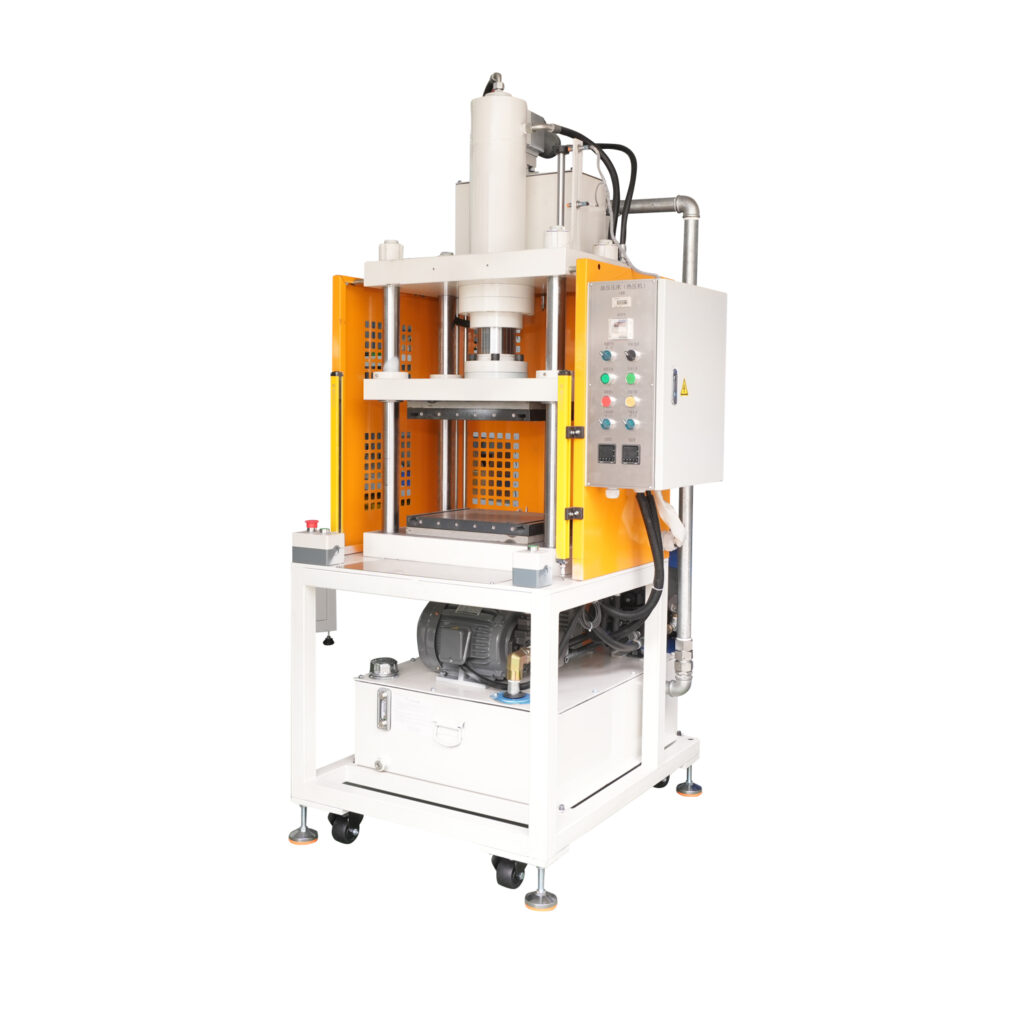
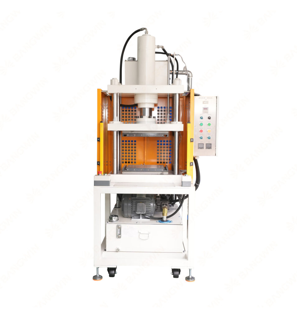
Vapor Chamber Hot Press Hydraulic Machine Guide Introduction Modern electronic devices generate more heat than ever before. Therefore, manufacturers need efficient thermal management solutions. Vapor chambers offer an effective way to spread concentrated heat across a larger surface. However, manufacturing these components requires precise forming, pressing, and dimensional control. A Vapor Chamber Hot Press Hydraulic Machine helps manufacturers achieve consistent chamber shapes and controlled pressing results. The machine combines hydraulic pressure, controlled heating, precision tooling, and automated operation. Consequently, manufacturers can improve vapor chamber flatness, structural consistency, and production efficiency. Furthermore, hot pressing can support several manufacturing stages within a vapor chamber production process. This equipment can work alongside forming, sintering, laser sealing, vacuum, and testing equipment. Therefore, it plays an important role in an integrated vapor chamber production line. This guide explains the machine structure, working principle, manufacturing process, advantages, applications, and selection criteria. It also explains how cncoolingthermal supports vapor chamber manufacturing equipment solutions. 1. What Is a Vapor Chamber Hot Press Hydraulic Machine? A Vapor Chamber Hot Press Hydraulic Machine uses controlled pressure and heat to process vapor chamber components. The equipment typically includes a hydraulic pressing system, heating system, precision tooling, control cabinet, and safety structure. First, operators place the vapor chamber component inside the dedicated fixture. Next, the machine applies controlled pressure. Meanwhile, the heating system maintains the required processing temperature. Then, the hydraulic system maintains the programmed pressure for a defined period. Finally, the machine releases pressure and allows the component to continue to the next process. As a result, manufacturers can achieve more consistent dimensions across production batches. The machine can support different chamber designs through customized tooling. Therefore, manufacturers should select tooling according to product dimensions and manufacturing requirements. Typical Functions A vapor chamber hot press machine can support: Chamber flattening Shape correction Thickness control Surface flattening Component forming Structural stabilization Assembly pressing Controlled hot pressing However, the exact function depends on the vapor chamber design. Consequently, buyers should define the intended process before selecting the equipment. 2. Why Hot Pressing Matters in Vapor Chamber Manufacturing Vapor chambers require precise geometry to deliver consistent thermal performance. Even small dimensional differences can affect contact quality and assembly compatibility. Therefore, manufacturers need controlled forming and pressing processes. Hot pressing combines pressure and temperature during a controlled manufacturing cycle. The combination can help improve dimensional consistency for suitable vapor chamber designs. Furthermore, hydraulic systems can deliver stable pressing force. Consequently, manufacturers can achieve repeatable processing conditions. Flatness Matters Flatness plays an important role in many vapor chamber applications. For example, CPU and GPU cooling assemblies require close contact between the vapor chamber and heat source. Poor flatness can increase contact resistance. Therefore, manufacturers often place strong emphasis on dimensional control. Thickness Matters Ultra-thin vapor chambers require particularly careful processing. Excessive pressure can cause unwanted deformation. Insufficient pressure can leave dimensional inconsistencies. Therefore, the machine must provide controlled pressure and suitable tooling. Consistency Matters Mass production requires repeatable results. Manual pressing can introduce variation between operators. In contrast, programmable hydraulic systems can repeat defined process parameters. Consequently, manufacturers can improve batch-to-batch consistency. 3. How Does a Vapor Chamber Hot Press Hydraulic Machine Work? The machine follows a controlled pressing cycle. The exact sequence depends on product requirements and machine configuration. Step 1: Product Loading First, the operator or automatic handling system loads the vapor chamber component. Next, the fixture positions the product accurately. Furthermore, locating pins or dedicated tooling can maintain consistent positioning. Therefore, accurate loading provides a stable foundation for the pressing process. Step 2: Tool Closing The hydraulic system moves the upper tooling toward the product. The controller manages the movement according to the programmed sequence. Additionally, sensors can monitor the tool position. Consequently, the machine can control the closing process accurately. Step 3: Heating Next, the heating system raises the tooling or workpiece to the required temperature. Temperature controllers monitor the process continuously. Furthermore, multiple heating zones can provide more uniform temperature distribution. Therefore, manufacturers can maintain stable thermal conditions during pressing. Step 4: Hydraulic Pressing Once the system reaches the required conditions, hydraulic pressure increases. The machine applies the programmed force to the vapor chamber. Meanwhile, the control system monitors pressure and position. Consequently, the process can maintain stable pressing conditions. Step 5: Pressure Holding The hydraulic system maintains pressure for a defined period. This stage allows the material and structure to stabilize. However, pressure and holding time depend on the product design. Therefore, manufacturers should validate these parameters through production trials. Step 6: Pressure Release After the holding stage, the machine gradually releases hydraulic pressure. The tooling then returns to its original position. Furthermore, controlled release can reduce unwanted mechanical stress. Step 7: Product Unloading Finally, the operator or automatic handling system removes the processed component. The chamber then moves to the next manufacturing stage. For example, the next step may involve laser sealing, vacuum processing, or thermal testing. 4. Main Components of the Machine A reliable hydraulic hot press machine combines several systems. Each system contributes to pressing precision, stability, and production efficiency. 4.1 Hydraulic System The hydraulic system generates the required pressing force. It usually includes a hydraulic pump, valves, cylinders, pressure sensors, and related components. Furthermore, the controller manages pressure according to the selected recipe. Therefore, hydraulic stability directly affects pressing consistency. 4.2 Heating System The heating system provides controlled thermal energy. Depending on the machine design, manufacturers may use electrical heating elements or other suitable heating methods. Temperature sensors monitor the process. Additionally, controllers maintain the selected temperature range. Consequently, the system can support stable hot pressing conditions. 4.3 Precision Tooling Tooling determines the final geometry of the processed component. Therefore, tooling design requires careful attention. Manufacturers can customize the fixture according to chamber dimensions and product structure. Furthermore, replaceable tooling can improve production flexibility. 4.4 Hydraulic Cylinder The hydraulic cylinder converts hydraulic pressure into mechanical pressing force. Its size depends on the required force and operating conditions. Additionally, cylinder movement must remain stable during the pressing cycle. Consequently,

Vapor Chamber Hot Press Hydraulic Machine Guide Read More »

the application of vapor chambers

Vapor Chamber Fully Automatic Laser Sealing Machine Guide

Vapor Chamber Fully Automatic Laser Sealing Machine Guide 1. Introduction to Vapor Chamber Fully Automatic Laser Welding Machine 1. What Is Vapor Chamber Fully Automatic Laser Sealing Machine? A Vapor Chamber Fully Automatic Laser Sealing Machine directs focused laser energy toward weld joints for vapor chamber sealing. Manufacturers typically employ this technology to seal copper enclosures or charging ports when manufacturing vapor chambers. The machine integrates several subsystems including laser source, precision motion system, workholding fixtures, and controls. The system positions the vapor chamber within loading fixtures. The laser traverses along the programmed welding path. The focused energy melts the joining surfaces together to form a metallurgical bond. Once completed, the machine completes the cycle and readies parts for inspection or unloading. Consequently, vapor chamber manufacturers can perform repeatable welds with less manual operation. Key Functions Typical applications of this equipment require support for multiple manufacturing functions such as: – Welding copper components with accuracy – Automating laser movement along a fixed path – Providing repeatable sealing quality – Eliminating excessive operator handling – Programming weld paths and parameters – Integrating into automated material transfer systems – Repeatability of welding cycles – Monitoring process conditions and quality assurance Moreover, many manufacturers can benefit from automation when producing high volumes of vapor chambers. However, appropriate material and component preparation, sealing parameters, and joint design remain critical to successful welds. 2. How Does Automatic Laser Sealing Machine Work? Automation of laser sealing processes utilizes a concentrated beam of laser energy and controlled movement between weld surfaces. As mentioned previously, the primary benefit of laser welding is the ability to precisely deliver energy to a small targeted area. This allows manufacturers to establish weld geometry through a combination of laser power, focus, and travel speed. Step 1: Automatic Loading Initially, the operator loads the vapor chamber into the sealing machine. Next, fixtures secure the part for welding and locate the weld joint to the desired position on the laser processing path. Therefore, ensuring rigid workholding can help improve weld accuracy. Step 2: Position Detection The controller verifies proper part location before welding begins. Cameras or position sensors may also assist with weld alignment depending on machine configuration. Once in place, the controller also loads the specific welding program. Therefore, the system is now ready to perform the sealing operation. Step 3: Laser Welding The laser generates the appropriate amount of energy to commence welding. A focused laser beam then heats the joining copper edges to form a molten weld pool. At the same time, the motion system moves the laser beam along the programmed sealing path. As the molten weld pool cools, it creates a continuous weld bead between both workpieces. Step 4: Cooling and Inspection As mentioned above, the weld joint then cools and solidifies to form a metallurgical bond. Optical inspection systems may review weld bead appearance and geometry. Leak testing may also occur to verify sealing requirements. Therefore, if defects are detected, manufacturers can identify and address concerns before moving the part to further production stages. Step 5: Automatic Unloading The machine then unlocks and releases the finished vapor chamber. An operator or robot system then moves the chamber towards the next production station. As a result, automating material transfer reduces repetitive operator tasks. 3. Vapor Chamber Fully Automatic Laser Welding Machine Components Different mechanical and electrical systems comprise a fully automated laser welding machine. Understanding how each component works together can help designers establish production requirements and equipment specifications. 3.1 Laser Source The laser generates heat to form weld beads on vapor chamber joints. Most industrial laser sealing systems use fiber lasers due to their energy efficiency and lightweight design. However, copper is a reflective material with high thermal conductivity. Therefore, choosing the proper laser and welding parameters can be challenging. 3.2 Laser Welding Head The welding head focuses and directs laser energy to the workpiece. Specific optics also allow manufacturers to adjust beam diameter and focus depth. Some laser welding heads also include protective optics and surveillance capabilities. As a result, the welding head significantly influences weld repeatability. 3.3 Precision Motion System Motors and guides enable relative movement between the weld joint and laser source. Therefore, servo motors and precision guides allow the laser to follow a pre-programmed path. Furthermore, advanced motion controllers allow synchronization of feed rates and weld paths. Consistent motion allows for even weld bead formation. 3.4 Automatic Positioning System Fixtures hold vapor chamber components in place during welding. Furthermore, positioning aids limit movement within the weld joint. Vision systems can also aid in adjusting misaligned workpieces. As a result, proper part location ensures repeatable weld accuracy. 3.5 PLC Control System A programmable logic controller (PLC) synchronizes system motion and executes welding programs. First, the controller activates the movement sequences and safety features. Next, the PLC performs the welding operation based on the chosen program. Additionally, controllers can log alarms and process details during production. As a result, operators can adjust machine functions using a centralized control screen. 3.6 Human Machine Interface (HMI) Manufacturers can access machine functions and reports using the HMI or touchscreen interface. For instance, users can initiate specific welding programs and monitor system alarms. Moreover, proper credentials allow operators to change relevant machine settings. Therefore, a user-friendly interface allows operators to quickly manage equipment functions. 3.7 Cooling System Cooling prevents overheating of the laser source and optical system. As a result, industrial laser welding machines require proper cooling methods to protect internal components. Some systems use a water chiller to regulate temperatures. Moreover, temperature sensors allow monitoring of machine conditions. 3.8 Safety Protection System Lasers create optical, burn, and electrical hazards within the workplace. Therefore, manufacturers should design proper machine guarding and safety interlocks. Additionally, review emergency stops, fume extraction systems, and laser safety standards. For more information, please visit our Industrial Laser Safety Standards page. 4. Features and Benefits of Vapor Chamber Fully Automatic Laser Welding Machine 4.1 High Welding Accuracy Because laser welding focuses energy into a small

Vapor Chamber Fully Automatic Laser Sealing Machine Guide Read More »

vapor chamber hot press hydraulic machine

Vapor chamber production line

Vapor chamber production line Vapor Chamber Production Line: Complete Manufacturing Guide Introduction A vapor chamber production line helps manufacturers create advanced cooling components for modern electronic devices. These components support efficient heat transfer across compact surfaces. Today, processors, graphics cards, and power electronics generate significant heat during operation. Therefore, manufacturers need reliable thermal solutions to maintain performance and stability. Vapor chambers use phase-change technology to spread heat efficiently. Unlike conventional metal plates, they transport heat through evaporation, vapor movement, and condensation. Consequently, manufacturers increasingly explore automated equipment for consistent vapor chamber manufacturing. A modern production system combines precision cutting, forming, cleaning, sintering, welding, vacuum processing, and thermal testing. Each stage directly influences product quality. Furthermore, automation improves process repeatability and reduces manual handling. cncoolingthermal provides information about vapor chamber manufacturing equipment and thermal production solutions through its website, cncoolingthermal.com. This guide explains the complete manufacturing process, essential machinery, production considerations, and equipment selection strategies. 1. What Is Vapor Chamber Production Equipment? Essentially, a vapor chamber production line consists of dedicated machinery used to produce flat sealed two-phase heat spreaders. Production machines commonly work with copper foil, wick structures, working fluid, and sealing technology. Machines usually finish machining the metallic parts of the assembly first. Then forming equipment creates the internal structures needed to match your design. The vapor chamber production line then incorporates any necessary wick structures and features. Afterwards, welding machines seal the enclosure as dictated by your manufacturing specifications. Vacuum systems, fluid charging stations, and/or testing equipment finish creating your finished vapor chamber. Production lines can also include automatic loading systems, robotic part handling, and integrated process monitoring solutions. With everything working together, manufacturers experience increased throughput with highly repeatable build conditions. Objectives of Production Typically, production machines help manufacturers meet several goals: Achieve repeatable vacuum levels Ensure uniform wick structures Control working fluid levels Optimize thermal performance Reduce welding failures Enable repeatable mass production Decrease manufacturing waste Because of this, proper equipment selection becomes critical to your success. 2. How Do Vapor Chambers Work? Vapor chambers spread heat through evaporation and condensation that occurs inside the device. Heat is applied to the vapor chamber, which causes the internal fluid to evaporate by absorbing heat. Vapor then moves to cooler areas of the vapor chamber and condenses by releasing heat. The wick helps transport liquid back to the heat source via capillary pressure. With this cycle occurring throughout the entire surface, the heat is effectively spread across the vapor chamber. Components of Vapor Chambers Cover and base: Copper covers provide structure and thermal contact on both sides. Capillary pump: The wick pumps liquid from the cold regions to the hot regions by capillary action. Liquid: Liquid absorbs heat when turning to vapor and releases heat when condensing back to a liquid. Spiders: The support structures reduce the likelihood of the enclosure bowing. Enclosure: The cavity of the vapor chamber seals in fluid and allows for two-phase heat transfer. Because of this, manufacturers must take great care when choosing materials, designing enclosure geometry, and executing clean builds with strong seals. Vapor Chamber vs. Heat Sink While traditional heat sinks conduct heat through solid metal, vapor chambers transport heat using conduction and phase-change. This means vapor chambers are capable of evening out temperature variations across a given heat-spreading surface. Keep in mind, real world results will vary based on chamber design, thermal load, chamber orientation, and more. View our heat pipe technology page for more detailed information. 3. Detailed Vapor Chamber Production Process A simplified representation STEP 1 – Material Cutting STEP 2 – Cleaning & Forming STEP 3 – Wick Preparation STEP 4 – Sintering STEP 5 – Assembly & Welding STEP 6 – Vacuum Degassing STEP 7 – Fluid Charging & Sealing STEP 8 – Thermal Testing A simplified workflow. Not every production line uses the same equipment or in the same order. 3.1 Cutting and Preparing Base Material Manufacturers source copper sheets based on product size and performance targets. Cutting machinery sections the upper and lower plates based on design specifications. In addition, manufacturers evaluate material thickness, flatness, and surface finish. Cutting to size allows for more accurate forming and welding tolerances. Internal Link: [Automatic Casing Cutter] Link to product page. 3.2 Cleaning Copper Sheets Post-cutting, copper surfaces often contain oil residue, particles, and other contaminants. Cleaning machinery removes surface impurities before assembly. In addition, clean surfaces improve weldability and minimize internal contamination. Ultra-sonic cleaning and controlled drying may be used for some applications. Achieving a contaminant-free surface allows for more consistent wick characteristics and seal performance. 3.3 Forming the Vapor Chamber Copper sheets now undergo the forming process to achieve the proper shape. Stamping or pressing equipment can accomplish this task. Features like internal support structures and fluid passages may also form during this step. Dimensional accuracy during the forming process helps ensure proper internal clearance and structural integrity. 3.4 Preparing the Wick Structure Preparing the wick structure is critical to overall vapor chamber performance. The wick typically consists of sintered copper powder, metal mesh, or other specialized structures. If using sintered powder, material is applied to specific surfaces within the vapor chamber. Equipment may spray or brush copper powder onto chamber surfaces. The application method allows manufacturers to control powder coverage thickness and placement. Uniform application allows for consistent capillary action in the wick structure. Internal Link: [Automatic Powder Filling Machine] Link to product page. 3.5 Vacuum Sintering Process After applying copper powder, sintering occurs within a specialized furnace. Temperature and time combine to create a porous wick structure. Too much heat or too long can cause the copper particles to lose their porosity. Internal Link: [Vacuum Sintering Furnace] Link to product page. 3.6 Vapor Chamber Assembly and Welding Components now come together for welding either automatically or manually. Assemblies may have their internal structures placed before welding. Automated laser welding perfectly joins the vapor chamber together. Automated welding allows for consistent welding speed, power, and path. However, laser welding parameters should be set

Vapor chamber production line Read More »