Uncategorized

copper heat pipe bending machine

Heat Pipe Production Line: Complete Manufacturing Guide

Heat Pipe Production Line: Complete Manufacturing Guide 1. What Is a Heat Pipe Production Line? A Heat Pipe Production Line is a manufacturing system that uses specialized equipment to produce heat pipes. It covers the main production stages, from raw material preparation to finished product inspection. A typical production line may include: Copper tube cutting machine Heat pipe necking machine Heat pipe powder filling machine Vacuum sintering furnace Heat pipe multi-station dry-out tester Vacuum degassing machine Heat pipe filling and welding machine Automatic tail cutting machine Leak testing equipment Thermal performance tester The exact equipment configuration depends on heat pipe dimensions, wick structure, working fluid, and production capacity. For example, a sintered copper powder wick requires powder filling and sintering equipment. A mesh wick requires mesh preparation and assembly equipment instead. A well-designed production line should match the actual manufacturing process. This helps avoid unnecessary equipment investment. 1.1 Main Functions of a Heat Pipe Production Line A complete production line supports several important manufacturing functions. Tube preparation: Cutting and necking machines prepare copper tubes for later processing. Wick structure manufacturing: Specialized equipment creates or installs the internal liquid return structure. Powder filling and sintering: Powder filling machines distribute copper powder. Sintering furnaces create porous wick structures. Cleaning and drying: These processes remove contaminants and residual moisture. Vacuum processing: Vacuum equipment removes unwanted gases from the internal space. Working-fluid filling: Filling equipment introduces the specified quantity of working fluid. Sealing and cutting: Welding and tail cutting equipment complete the tube structure. Quality inspection: Leak testing and thermal performance testing evaluate finished product quality. 2. How Does Heat Pipe Manufacturing Work? Heat pipe manufacturing involves several connected processes. Each stage must match the product’s engineering design. A typical copper heat pipe production process includes the following steps. 2.1 Copper Tube Preparation Manufacturers begin by selecting suitable copper tubes. The tube material, outer diameter, wall thickness, and length must meet product specifications. The preparation process may include: Raw material inspection Tube cutting End preparation Dimensional inspection Surface cleaning Accurate tube dimensions support consistent downstream processing. 2.2 Wick Structure Manufacturing The wick structure returns condensed working fluid toward the evaporator section. Common wick structures include: Sintered copper powder Copper mesh Axial grooves Composite wick structures Each structure requires a different manufacturing method. Sintered powder structures require powder filling and controlled sintering. Mesh structures require accurate cutting and installation. Grooved structures need suitable internal forming or machining processes. The selected wick structure should match the product’s thermal requirements and operating conditions. 2.3 Powder Filling For sintered wick heat pipes, manufacturers introduce copper powder into the tubes. Powder distribution affects the internal wick structure. Uneven filling may cause inconsistent thermal performance. A dedicated Heat Pipe Powder Filling Machine helps control powder delivery. Important factors include powder properties, filling quantity, tube dimensions, and filling consistency. 2.4 Sintering Process After powder filling, the workpiece enters a suitable sintering process. The furnace applies controlled thermal conditions to bond powder particles. This creates a porous copper structure. Sintering conditions depend on powder characteristics, tube material, and product design. A suitable Vacuum Sintering Furnace supports controlled processing conditions. 2.5 Tube Forming and Necking Some heat pipe designs require reduced tube diameters at specific positions. A necking machine forms the tube according to the required geometry. This process may prepare the tube for later sealing or other manufacturing operations. Manufacturers should control necking dimensions and avoid unwanted tube deformation. 2.6 Cleaning and Drying Manufacturers must remove contaminants and residual moisture before vacuum processing. Cleaning and drying serve different purposes. Cleaning removes unwanted substances from internal and external surfaces. Drying removes residual moisture. The appropriate method depends on tube material, wick structure, and manufacturing requirements. 2.7 Vacuum Evacuation and Degassing Vacuum evacuation removes unwanted gases from the internal chamber. Degassing can also help remove gases released from internal materials during processing. These operations support a suitable internal environment for heat transfer. Manufacturers should distinguish degassing from cleaning, drying, working-fluid filling, and final sealing. 2.8 Working-Fluid Filling After suitable vacuum processing, manufacturers introduce the working fluid. Water is commonly used in copper heat pipes designed for appropriate operating temperatures. The filling quantity depends on tube dimensions, internal volume, wick structure, and product requirements. Manufacturers should establish filling parameters through engineering calculations and product validation. 2.9 Welding and Sealing After fluid filling, manufacturers complete the sealing process. A Heat Pipe Filling & Welding Machine can support fluid charging and sealing-related operations. The selected welding method should match tube material, wall thickness, joint geometry, and production requirements. 2.10 Tail Cutting and Final Testing Some manufacturing processes leave excess tube material after sealing. A tail cutting machine removes this material according to the product design. Finished heat pipes then undergo leak inspection and thermal performance testing. These tests help manufacturers evaluate sealing integrity and heat transfer characteristics. 3. Essential Machines in a Heat Pipe Production Line A complete Heat Pipe Production Line connects specialized machines into an organized workflow. Each machine performs a specific function. Manufacturers should select equipment according to their actual production requirements. 3.1 Heat Pipe Tube Cutting Machine A tube cutting machine prepares copper tubes to the required length. Accurate cutting supports consistent dimensions and downstream processing. Important selection factors include: Compatible tube diameters Supported wall thickness Cutting length range Cutting accuracy Edge quality Production capacity Manufacturers should test the machine using their actual tube materials. 3.2 Heat Pipe Necking Machine A necking machine reduces tube diameter at designated positions. It supports different heat pipe designs and sealing arrangements. Important considerations include: Tube diameter range Necking length Forming accuracy Tooling design Surface quality Process repeatability Suitable tooling helps reduce deformation and maintain dimensional consistency. 3.3 Heat Pipe Powder Filling Machine A powder filling machine introduces copper powder into heat pipe tubes. It is particularly important for sintered wick heat pipes. The machine should provide stable powder delivery and suitable filling control. Important evaluation points include: Powder compatibility Tube diameter range Filling quantity control Powder distribution Production speed Cleaning and maintenance Manufacturers should confirm

Heat Pipe Production Line: Complete Manufacturing Guide Read More »
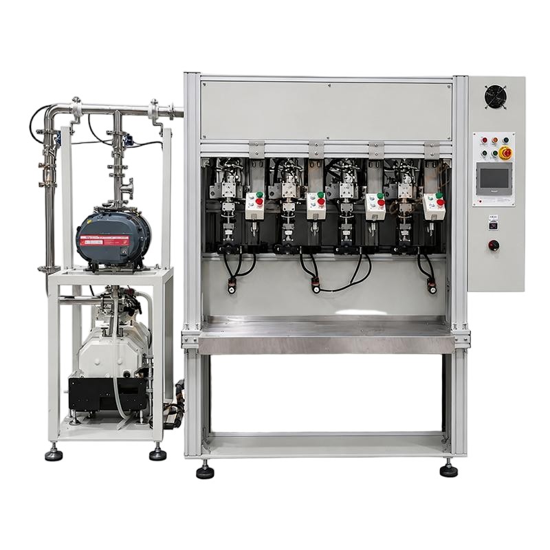
copper heat pipe bending machine

Heat Pipe Equipment Production Line: Complete Guide

Heat Pipe Equipment Production Line: Complete Guide 1. What Is a Heat Pipe Equipment Production Line? A Heat Pipe Equipment Production Line is a collection of specialized machines used to manufacture heat pipes. It supports different production stages, from raw tube preparation to finished product testing. A typical production line may include: Heat pipe tube cutting machine Heat pipe necking machine Heat pipe powder filling machine Vacuum sintering furnace Heat pipe multi-station dry-out tester Heat pipe vacuum degassing equipment Heat pipe filling and welding machine Heat pipe tail cutting machine Heat pipe leak testing equipment Heat pipe thermal performance tester The actual configuration depends on heat pipe design, wick structure, tube dimensions, working fluid, and production capacity. For example, a sintered copper powder wick requires powder filling and sintering equipment. A mesh or grooved wick may need a different manufacturing process. Manufacturers should define their product specifications before selecting individual machines. 1.1 Main Functions of a Heat Pipe Production Line A complete production line supports several important manufacturing functions. Tube preparation Cutting and necking machines prepare copper tubes for subsequent processing. Wick structure manufacturing Specialized equipment creates or installs the internal wick structure. The wick supports liquid return through capillary action. Powder filling and sintering For sintered wick heat pipes, powder filling equipment distributes copper powder. A sintering furnace creates the required porous structure. Cleaning and drying Dry-out equipment supports moisture removal and prepares workpieces for later processing. Vacuum evacuation and fluid filling Vacuum equipment removes unwanted gases. Filling equipment introduces the specified working fluid. Sealing and final processing Welding equipment seals the heat pipe. Tail cutting equipment removes excess tube material when required. Quality inspection Leak testing and thermal performance testing help verify finished product quality. 2. How Does Heat Pipe Manufacturing Work? Heat pipe manufacturing involves several connected processes. Each process must match the selected heat pipe design. A typical copper heat pipe production workflow may include the following stages. 2.1 Copper Tube Preparation Manufacturers first select suitable copper tubes. The tube material, outer diameter, wall thickness, and length must match product specifications. The preparation process may include: Raw material inspection Tube cutting End preparation Dimensional inspection Surface cleaning Accurate tube dimensions support stable downstream processing. 2.2 Wick Structure Manufacturing The wick structure returns condensed working fluid toward the evaporator section. Common wick structures include: Sintered copper powder Copper mesh Axial grooves Composite wick structures Each structure requires a suitable manufacturing process. Sintered powder structures require powder filling and controlled sintering. Mesh structures require accurate cutting and installation. Grooved structures require suitable internal forming or machining methods. The wick design should match the required heat transfer performance and operating conditions. 2.3 Powder Filling For sintered wick heat pipes, manufacturers introduce copper powder into the tube. Powder distribution affects the internal wick structure. Uneven filling may cause inconsistent thermal performance. A dedicated Heat Pipe Powder Filling Machine can help control powder delivery. Important process factors include powder properties, filling quantity, tube dimensions, and filling consistency. 2.4 Sintering Process After powder filling, the tube enters a suitable sintering process. The furnace applies controlled temperature conditions to bond powder particles. This creates a porous copper structure. The required sintering conditions depend on powder characteristics, tube material, and product design. A suitable Vacuum Sintering Furnace can support controlled processing conditions. 2.5 Tube Forming and Necking Some heat pipe designs require reduced tube diameters at specific positions. A necking machine forms the tube according to the required geometry. This process may prepare the tube for sealing or other downstream operations. Manufacturers should control necking dimensions and avoid unwanted tube deformation. 2.6 Cleaning and Drying Manufacturers must remove unwanted contaminants and residual moisture before vacuum processing. Cleaning and drying are separate process requirements. Cleaning removes contaminants from the internal and external surfaces. Drying removes residual moisture. The exact method depends on the tube material, wick structure, and production process. 2.7 Vacuum Evacuation and Degassing Vacuum evacuation removes unwanted gases from the heat pipe. Degassing can also help remove gases released from internal materials during processing. These operations support a suitable internal environment for heat transfer. Manufacturers should distinguish degassing from cleaning, drying, fluid filling, and final sealing. 2.8 Working-Fluid Filling After suitable vacuum processing, manufacturers introduce the working fluid. Water is commonly used in copper heat pipes designed for appropriate operating temperatures. The filling quantity depends on tube dimensions, internal volume, wick structure, and product requirements. Manufacturers should establish filling parameters through engineering calculations and product validation. 2.9 Welding and Sealing After fluid filling, the heat pipe requires reliable sealing. A Heat Pipe Filling & Welding Machine can combine fluid filling and sealing-related operations, depending on its configuration. The selected welding method should match tube material, wall thickness, joint geometry, and production requirements. 2.10 Tail Cutting and Final Testing Some manufacturing processes leave excess tube material after sealing. A tail cutting machine removes this unwanted section according to the product design. Finished heat pipes then undergo leak inspection and thermal performance testing. These tests help manufacturers evaluate product reliability and heat transfer characteristics. 3. Essential Machines in a Heat Pipe Equipment Production Line Each machine performs a specific function. Manufacturers should select equipment according to their actual production workflow. 3.1 Heat Pipe Tube Cutting Machine A tube cutting machine prepares copper tubes to the required length. Accurate cutting supports consistent product dimensions and downstream processing. Important selection factors include: Compatible tube diameters Supported wall thickness Cutting length range Cutting accuracy Edge quality Production capacity Manufacturers should test the machine using their actual tube materials. 3.2 Heat Pipe Necking Machine A necking machine reduces the tube diameter at designated positions. It can support different heat pipe designs and sealing arrangements. Important considerations include: Tube diameter range Necking length Forming accuracy Tooling design Surface quality Repeatability Suitable tooling helps reduce deformation and maintain dimensional consistency. 3.3 Heat Pipe Powder Filling Machine A powder filling machine introduces copper powder into heat pipe tubes. It is particularly important for manufacturing sintered wick heat pipes. The machine should

Heat Pipe Equipment Production Line: Complete Guide Read More »

automatic heat pipe production line

Vapor Chamber Production Line: Complete Guide

Vapor Chamber Production Line: Complete Guide 1. What Is a Vapor Chamber Production Line? A Vapor Chamber Production Line is an integrated manufacturing system for producing flat heat transfer components. It uses specialized equipment to process metal plates, create internal structures, assemble chambers, introduce working fluid, and complete final testing. A typical production line may include: Metal plate cutting equipment Plate cleaning equipment Chemical etching or internal structure processing equipment Support pillar processing equipment Hot press hydraulic machine Automatic sand blasting machine Laser welding machine Laser sealing machine Vacuum filling and welding machine Degassing machine Water bath bubble leak tester Thermal performance tester The actual equipment configuration depends on vapor chamber dimensions, thickness, internal structure, material, and production capacity. For example, an ultra-thin vapor chamber may require different processing and sealing methods from a larger industrial vapor chamber. Therefore, manufacturers should define their product specifications before selecting machines. 1.1 Main Functions of a Vapor Chamber Production Line A complete production line supports several important manufacturing objectives. Accurate plate preparation Cutting and surface preparation equipment helps maintain consistent dimensions and surface conditions. Internal structure manufacturing Etching, forming, or other suitable processes create the internal wick structure. The wick supports working-fluid circulation. Controlled chamber assembly Assembly and pressing equipment help position plates and internal support structures. Reliable bonding and sealing Laser welding and other suitable joining methods help create a sealed chamber. Controlled vacuum processing Vacuum equipment removes unwanted gases and prepares the chamber for working-fluid filling. Consistent performance testing Leak testing and thermal performance evaluation help verify finished product quality. 2. How Does Vapor Chamber Manufacturing Work? Vapor chamber manufacturing involves several connected processes. Each stage affects the final component’s thermal performance and reliability. The exact workflow varies according to product design and manufacturing technology. However, many production processes follow a similar sequence. 2.1 Metal Plate Preparation Manufacturers begin by selecting suitable metal plates. Copper is widely used because of its thermal conductivity and compatibility with common water-based vapor chamber designs. The preparation process may include: Raw material inspection Plate cutting Surface cleaning Thickness inspection Flatness inspection Edge preparation Accurate plate dimensions support consistent assembly. Surface condition also affects bonding and sealing quality. 2.2 Internal Wick Structure Manufacturing The wick structure transports working fluid from the condenser region to the evaporator region. Common wick structures include: Sintered copper powder Copper mesh Grooved structures Composite wick structures Different structures require different manufacturing methods. For example, sintered powder structures may require powder preparation, distribution, and sintering. Mesh structures require accurate cutting and positioning. The selected wick structure should match the vapor chamber’s thermal requirements and available manufacturing processes. 2.3 Support Pillar Manufacturing and Positioning Support pillars help maintain the internal chamber gap. They also resist deformation caused by external pressure and internal vacuum conditions. Their dimensions and positions must match the product design. Manufacturers should consider pillar height, spacing, bonding, and compatibility with the chamber structure. Poor pillar positioning may affect chamber thickness or internal vapor space. 2.4 Plate Assembly and Bonding The upper and lower plates must be assembled with the internal wick and support structures. Manufacturers need accurate positioning to avoid internal structural defects. Suitable bonding or welding processes create the required chamber structure. The selected method depends on plate thickness, material, joint design, and production requirements. 2.5 Cleaning and Drying Cleaning removes contaminants from internal surfaces. These contaminants may affect working-fluid behavior, wetting characteristics, bonding quality, or long-term reliability. Drying removes residual moisture and prepares the chamber for vacuum processing. Manufacturers should choose cleaning and drying methods according to material compatibility and process requirements. 2.6 Vacuum Evacuation and Working-Fluid Filling After chamber preparation, vacuum equipment removes unwanted gases from the internal space. Manufacturers then introduce a specified quantity of working fluid. Water is common in copper-water vapor chambers designed for suitable operating conditions. The required fluid quantity depends on internal volume, wick structure, chamber geometry, and thermal requirements. Manufacturers should establish filling parameters through engineering calculations and product testing. 2.7 Final Sealing and Performance Testing After filling, manufacturers complete the sealing process. They then inspect the finished chamber for leakage, deformation, and other defects. Thermal performance testing evaluates heat transfer under defined operating conditions. These inspections help manufacturers verify product quality before shipment. 3. Essential Machines in a Vapor Chamber Production Line Each machine performs a specific manufacturing function. These machines must also work together to maintain a balanced production process. 3.1 Vapor Chamber Plate Cutting Machine A plate cutting machine prepares metal sheets or plates according to the required dimensions. Accurate cutting provides a consistent starting point for later processing. Important selection factors include: Supported plate materials Plate thickness range Cutting dimensions Cutting accuracy Edge quality Production capacity Manufacturers should evaluate the machine using their actual material specifications. 3.2 Automatic Sand Blasting Machine An automatic sand blasting machine treats metal surfaces through controlled abrasive processing. Depending on the process design, surface treatment can help prepare plates for subsequent manufacturing operations. Important factors include: Processing width Abrasive material Surface treatment consistency Dust collection Conveyor speed Material compatibility Manufacturers should define the required surface condition before selecting equipment. Surface blasting should not replace dedicated cleaning processes when chemical or particulate contamination remains. 3.3 Vapor Chamber Internal Structure Processing Equipment Internal wick structures are essential to vapor chamber operation. Depending on the design, manufacturers may use etching, powder processing, mesh assembly, or other methods. For sintered structures, powder processing and sintering equipment help create porous copper layers. For mesh structures, cutting and positioning equipment supports accurate assembly. The manufacturing method should match the required wick geometry and thermal performance. 3.4 Vapor Chamber Hot Press Hydraulic Machine A hot press hydraulic machine applies controlled pressure and, where specified, heat during a manufacturing process. It may support forming, bonding, or other operations depending on the product design and machine configuration. Important selection factors include: Pressing force Working area Temperature control Pressure stability Positioning accuracy Cycle time Manufacturers should confirm the machine’s intended function before including it in the production line. 3.5 Vapor Chamber

Vapor Chamber Production Line: Complete Guide Read More »

automatic secondary degassing & tail welding machine for heat pipe

Heat Pipe Production Line: Complete Manufacturing Guide

Heat Pipe Production Line: Complete Manufacturing Guide 1. What Is a Heat Pipe Production Line? A Heat Pipe Production Line is a manufacturing system that uses specialized equipment to produce heat pipes. Each machine handles a specific process, from preparing metal tubes to testing finished products. A typical production line may include: Automatic tube cutting machine Tube cleaning equipment Heat pipe necking machine Powder filling machine Sintering furnace Heat pipe dry-out equipment Vacuum filling and welding machine Automatic tail cutting machine Leak testing equipment Thermal performance tester Not every manufacturer needs all these machines. The required configuration depends on product specifications, wick technology, production volume, and quality requirements. For example, a sintered copper heat pipe requires powder filling and sintering. A grooved heat pipe uses a different internal structure and manufacturing method. Therefore, manufacturers should define their product requirements before selecting equipment. 1.1 Main Functions of a Heat Pipe Production Line A complete production line supports several important manufacturing objectives. Accurate tube processing Cutting and forming machines prepare tubes according to specified dimensions. Consistent processing also supports downstream operations. Stable wick manufacturing The wick structure provides the capillary force needed to return working fluid. Its quality directly affects heat pipe operation. Controlled internal preparation Cleaning, drying, and vacuum processing help prepare the internal environment. Precise working-fluid filling Filling equipment introduces the required fluid quantity according to product specifications. Reliable sealing Suitable welding equipment closes the heat pipe and helps maintain its internal condition. Consistent performance testing Inspection and thermal performance testing help verify finished product quality. 2. How Does Heat Pipe Manufacturing Work? Heat pipe manufacturing involves several connected processes. Each stage requires suitable equipment and controlled operating conditions. The exact workflow varies with product design. However, many manufacturing processes follow a similar sequence. 2.1 Tube Preparation Manufacturers begin by selecting suitable metal tubes. Copper is widely used in heat pipe manufacturing because of its thermal conductivity and compatibility with water-based working fluids. The preparation process may include: Raw material inspection Tube cutting End preparation Necking or forming Dimensional inspection Surface cleaning Accurate tube dimensions help ensure consistent production. They also reduce problems during filling and sealing. 2.2 Wick Structure Manufacturing The wick structure transports working fluid from the condenser section to the evaporator section. Common wick structures include: Sintered powder wick Grooved wick Screen mesh wick Composite wick Each structure requires different manufacturing processes. For sintered powder heat pipes, manufacturers introduce metal powder into the tube. They then use controlled sintering conditions to create a porous structure. Powder characteristics and sintering parameters influence the final wick properties. 2.3 Cleaning and Drying Cleaning removes contaminants from internal surfaces. These contaminants may affect fluid behavior, product reliability, and manufacturing consistency. Drying removes residual moisture and other unwanted substances. Manufacturers should select suitable methods according to tube material, wick structure, and process requirements. 2.4 Vacuum Processing Vacuum processing removes unwanted gases from the heat pipe. Non-condensable gases can interfere with normal evaporation and condensation. Therefore, evacuation plays an important role in heat pipe manufacturing. The required vacuum conditions depend on product design and process validation. A vacuum pump’s rated ultimate pressure does not automatically represent the actual pressure inside a connected workpiece. 2.5 Working-Fluid Filling After evacuation, manufacturers introduce a specified quantity of working fluid. Water is common in copper-water heat pipes designed for suitable operating temperatures. Other working fluids may serve different applications. The filling quantity depends on internal volume, wick structure, working fluid, and operating conditions. Manufacturers should establish filling parameters through engineering calculations and product testing. 2.6 Sealing and Final Inspection The filling end must be sealed after the working fluid enters the heat pipe. Manufacturers may use resistance welding or laser welding. The suitable method depends on material, wall thickness, joint design, and production requirements. The finished product then undergoes leak testing and thermal performance evaluation. This process helps manufacturers verify product quality before shipment. 3. Essential Machines for Heat Pipe Production Each machine performs a specific function. The machines must also work together to maintain a balanced manufacturing process. 3.1 Heat Pipe Automatic Tube Cutting Machine An automatic tube cutting machine cuts metal tubes to the required length. Accurate cutting provides a consistent starting point for later manufacturing stages. It also helps reduce material waste. Important selection factors include: Supported tube diameter Cutting length range Cutting accuracy Material compatibility Burr control Production capacity Manufacturers should test the machine using their actual tube materials and dimensions. 3.2 Heat Pipe Necking Machine A heat pipe necking machine reduces the diameter of a selected tube section. This process can prepare the tube end for subsequent filling and sealing operations. The machine should provide stable positioning and controlled forming pressure. Incorrect forming parameters may cause deformation or damage. Therefore, manufacturers should validate the process using representative workpieces. 3.3 Heat Pipe Powder Filling Machine A powder filling machine introduces metal powder into the heat pipe tube. The powder can form a porous wick structure after sintering. Filling consistency helps manufacturers control the amount and distribution of powder. Important considerations include: Powder material compatibility Filling quantity control Powder distribution Tube positioning Handling efficiency Production consistency The required filling process depends on the product’s internal design. 3.4 Heat Pipe Sintering Equipment Sintering equipment heats the filled tube under controlled conditions. The process bonds powder particles and creates a porous structure. This structure supports capillary movement of working fluid. Sintering conditions depend on powder composition, particle size, tube material, and product design. Temperature uniformity and atmosphere control are important factors. Manufacturers should validate the resulting wick structure through appropriate inspection. 3.5 Heat Pipe Multi-station Dry-out Tester A multi-station dry-out tester supports the drying and preparation stages of production. Multiple stations allow manufacturers to process several workpieces within one cycle, depending on the machine configuration. Equipment functions can vary. Manufacturers should confirm whether the selected model includes heating, vacuum processing, temperature monitoring, or other functions. Key selection factors include: Number of stations Supported workpiece dimensions Temperature control Process repeatability Loading method Cycle time Drying and

Heat Pipe Production Line: Complete Manufacturing Guide Read More »
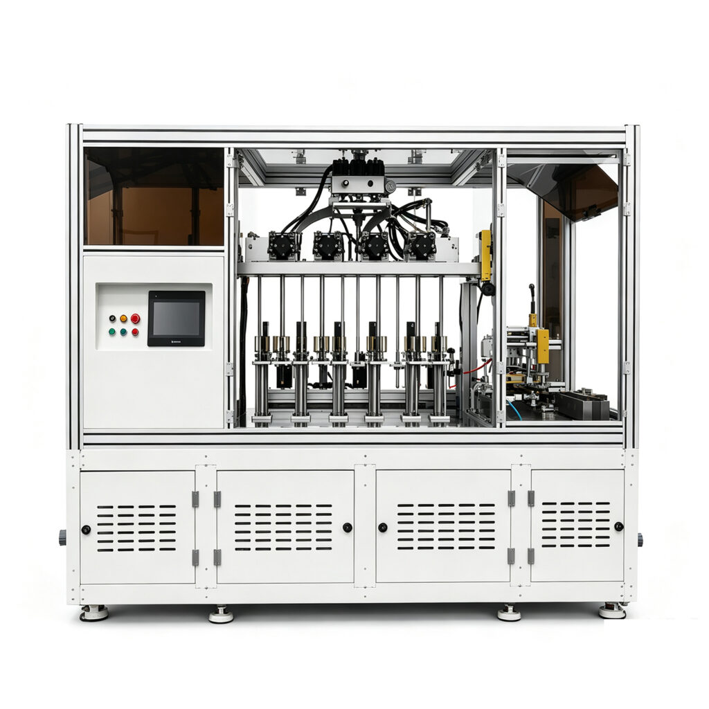
heat pipe straightening machine

Heat Pipe Equipment Production Line: Complete Guide

Heat Pipe Equipment Production Line: Complete Guide 1. What Is a Heat Pipe Equipment Production Line? A Heat Pipe Equipment Production Line is a group of specialized machines used to manufacture heat pipes. These machines support different stages, from tube preparation to final product testing. A typical production line may include: Tube cutting equipment Tube cleaning equipment Necking machines Powder filling machines Sintering equipment Heat pipe dry-out equipment Vacuum filling and welding machines Tail cutting machines Sealing equipment Thermal performance testing machines Not every manufacturer needs all these machines. The required configuration depends on the product design and manufacturing process. For example, a copper heat pipe with a sintered powder wick needs different processing equipment from a grooved heat pipe. Therefore, manufacturers should define their product specifications before selecting machines. 1.1 Main Functions of a Production Line An integrated production line supports several important manufacturing objectives. Consistent product dimensions Precision cutting and forming equipment helps maintain stable dimensions. This improves compatibility with downstream assembly processes. Controlled internal structures Powder filling and sintering equipment support the production of specific wick structures. These structures influence capillary performance and fluid circulation. Reliable vacuum processing Vacuum equipment helps remove non-condensable gases and prepare the internal environment. Accurate working-fluid filling Filling equipment controls the working-fluid quantity according to product requirements. Stable sealing quality Suitable welding and sealing equipment helps create reliable closed structures. Repeatable performance testing Thermal performance testing helps manufacturers evaluate finished products against defined requirements. 2. How Does Heat Pipe Manufacturing Work? Heat pipe manufacturing involves several connected processes. Each process influences the final product’s thermal performance and reliability. Although production methods vary, a common workflow includes tube preparation, wick manufacturing, cleaning, drying, evacuation, fluid filling, sealing, and testing. 2.1 Tube Preparation Manufacturers first prepare metal tubes according to the product design. Copper remains a common material for many heat pipe applications. Aluminum and other materials may also be used in specific designs. The preparation process may include: Tube cutting End preparation Dimensional inspection Surface cleaning Forming or bending Accurate tube preparation creates a stable foundation for subsequent manufacturing stages. 2.2 Wick Structure Manufacturing The wick structure returns working fluid from the condenser section to the evaporator section. Common wick structures include: Sintered powder wick Grooved wick Screen mesh wick Composite wick Different wick designs require different manufacturing processes. For sintered powder structures, manufacturers may use powder filling and high-temperature sintering equipment. The process must match the required material and pore structure. 2.3 Cleaning and Drying Cleaning removes contaminants from internal and external surfaces. These contaminants may affect wetting behavior, sealing quality, or long-term reliability. Drying removes residual moisture and other unwanted substances. The specific cleaning and drying methods depend on the tube material, wick structure, and process requirements. 2.4 Evacuation and Working-Fluid Filling After preparation, manufacturers evacuate the heat pipe to remove internal gases. They then introduce a specified amount of working fluid. Water is common for copper-water heat pipes used in suitable operating temperature ranges. Other working fluids may be necessary for different operating conditions and materials. The filling quantity must match the product design. Manufacturers should not apply one universal filling ratio to every heat pipe. 2.5 Sealing and Final Testing The manufacturer seals the filling end using a suitable welding or sealing process. The finished heat pipe then undergoes inspection and performance testing. Depending on customer requirements, testing may include: Dimensional inspection Leak testing Visual inspection Thermal resistance testing Heat transfer performance testing Reliability testing This workflow forms the basis of many modern heat pipe manufacturing operations. 3. Essential Machines in a Heat Pipe Equipment Production Line The equipment configuration depends on product specifications and production capacity. The following machines are commonly considered when planning a Heat Pipe Equipment Production Line. 3.1 Heat Pipe Automatic Tube Cutting Machine Tube cutting equipment prepares tubes to the required length. A suitable machine should support stable cutting quality and repeatable positioning. It should also minimize deformation and burr formation. Important selection factors include: Supported tube diameter Cutting length range Cutting accuracy Material compatibility Production capacity Loading and unloading method Manufacturers should evaluate the actual tube dimensions before selecting a cutting machine. 3.2 Heat Pipe Necking Machine A necking machine reduces the diameter of a selected tube section. This process can prepare the tube end for filling, welding, or other manufacturing operations. The machine should provide controlled forming pressure and consistent positioning. Excessive deformation may damage the tube or affect subsequent sealing. When choosing a necking machine, consider tube material, wall thickness, diameter, and necking geometry. 3.3 Heat Pipe Powder Filling Machine A powder filling machine introduces metal powder into the tube for sintered wick production. Accurate filling helps manufacturers control the amount and distribution of powder. This supports more consistent internal structures. Key considerations include: Powder material compatibility Filling quantity control Filling consistency Tube positioning Powder handling Production efficiency The required filling method depends on tube dimensions and wick design. 3.4 Heat Pipe Sintering Equipment Sintering equipment heats the filled tube under controlled conditions. The process bonds powder particles together and creates a porous structure. This structure helps transport working fluid through capillary action. Sintering conditions depend on powder composition, particle size, tube material, and product design. Temperature uniformity and atmosphere control are important factors. Manufacturers should validate the sintering process through product testing. 3.5 Heat Pipe Multi-station Dry-out Tester A multi-station dry-out tester supports the drying and preparation stages of heat pipe production. Multiple stations can help manufacturers process several workpieces within one production cycle. However, equipment functions vary by machine configuration. Manufacturers should confirm whether a specific model provides heating, vacuum processing, monitoring, or other functions. Important evaluation points include: Number of processing stations Supported workpiece dimensions Temperature control Process consistency Loading method Cycle time Drying should not be confused with final evacuation or working-fluid filling. These are separate processes with different objectives. 3.6 Heat Pipe Vacuum Filling and Welding Machine This machine supports evacuation, working-fluid filling, and sealing-related operations. It plays an important role in controlling the internal

Heat Pipe Equipment Production Line: Complete Guide Read More »

automatic secondary degassing & tail welding machine for heat pipe

Heat Pipe Filling & Welding Machine: Complete Guide

Heat Pipe Filling & Welding Machine: Complete Guide 1. What Is a Heat Pipe Filling & Welding Machine? A Heat Pipe Filling & Welding Machine is industrial equipment designed to introduce working fluid into a heat pipe and seal its filling opening. A conventional heat pipe contains three essential elements: Metal container: Provides the sealed structure. Wick structure: Returns condensed liquid toward the evaporator. Working fluid: Transfers heat through evaporation and condensation. During operation, the working fluid absorbs heat and evaporates. The vapor moves toward a cooler region and releases heat through condensation. The liquid then returns through the wick structure. This continuous cycle allows heat pipes to transfer thermal energy efficiently. However, the internal environment must meet the product’s design requirements. Manufacturers need to control fluid quantity, residual gases, and sealing quality. 1.1 Main Functions of the Machine A typical machine may perform several operations: Connect the heat pipe to the filling system. Evacuate residual gases when vacuum processing is integrated. Introduce a controlled quantity of working fluid. Seal the filling opening through a suitable welding process. Monitor operating parameters and production status. Not every machine includes all these functions. Some manufacturers use separate vacuum, filling, and welding stations. The correct configuration depends on product structure, production capacity, and process requirements. 1.2 Why Is Specialized Equipment Necessary? Manual filling and sealing can create inconsistent results. Operators must control several parameters during repetitive production. For example, different fluid quantities may produce different thermal behaviors. Unstable welding conditions may also cause leakage. Specialized equipment helps standardize these operations. It can reduce manual handling and improve production repeatability. For manufacturers with large production volumes, automation can also support more efficient workflows. 2. Understanding the Heat Pipe Filling Process Before selecting equipment, manufacturers should understand what happens inside a heat pipe during production. The filling process does not simply involve adding liquid to an empty tube. It requires preparation, evacuation, controlled charging, and sealing. 2.1 Working-Fluid Selection The working fluid must match the heat pipe’s operating temperature range and material system. Common choices include: Water: Widely used in heat pipes designed for suitable temperature ranges. Methanol: Used in certain lower-temperature applications. Other compatible fluids: Selected according to specific thermal and material requirements. Manufacturers should consider chemical compatibility, operating temperature, vapor pressure, and safety requirements. Fluid selection should follow the product design rather than a universal recommendation. 2.2 Determining the Filling Quantity The correct fluid quantity depends on the internal structure. Important factors include: Tube diameter and length. Internal volume. Wick material and pore structure. Evaporator and condenser dimensions. Working-fluid properties. Intended operating conditions. Insufficient fluid may contribute to local dry-out under certain operating conditions. Excessive fluid may reduce available vapor space and affect thermal behavior. Therefore, manufacturers should establish filling parameters through engineering calculations and production validation. 2.3 Why Vacuum Processing Matters Residual air and non-condensable gases can interfere with heat transfer. These gases may accumulate in the condenser section. They can reduce the effective heat transfer area. Vacuum evacuation helps remove unwanted gases before working-fluid charging. However, manufacturers should distinguish between the vacuum pump’s rated ultimate pressure and the actual pressure achieved inside a connected workpiece. Real production performance depends on system volume, leakage, temperature, connections, and pumping speed. 3. How Does the Filling and Welding Machine Work? The machine follows a controlled sequence. Its actual workflow depends on whether vacuum evacuation, fluid charging, and welding share one system. A common production process includes the following stages. 3.1 Step 1: Workpiece Preparation Operators prepare the heat pipe before connecting it to the filling machine. The tube should complete the required forming and internal preparation operations. The wick structure should also meet product specifications. Typical preparation includes: Tube cutting. Internal cleaning. Wick installation. Tube forming. Dry-out treatment. Workpiece inspection. Cleanliness matters because contamination can affect internal circulation and product reliability. 3.2 Step 2: Connection and Positioning The operator places the workpiece into the fixture. The filling connection must form a reliable seal. Poor connections may cause vacuum leakage or unstable fluid delivery. The fixture should hold the tube securely during evacuation and filling. For manufacturers producing different models, adjustable fixtures can reduce product changeover time. 3.3 Step 3: Vacuum Evacuation If the machine includes a vacuum system, it removes residual air and other unwanted gases. The process may involve: Connecting the workpiece. Opening the vacuum valve. Starting the vacuum pump. Monitoring pressure. Reaching the validated process condition. The required evacuation time depends on workpiece geometry, internal cleanliness, moisture content, and system design. Manufacturers should validate vacuum performance under actual production conditions. 3.4 Step 4: Working-Fluid Injection After the required preparation, the machine introduces working fluid. A controlled metering system helps maintain the specified charging quantity. The filling process should account for fluid properties and product dimensions. Important parameters include: Target fluid quantity. Filling time. Fluid temperature, where relevant. Metering repeatability. Pipeline cleanliness. Workpiece positioning. Manufacturers should define acceptable tolerances based on product specifications. 3.5 Step 5: Welding and Sealing After filling, the machine seals the filling opening. Possible methods include resistance welding and laser welding. The choice depends on tube material, thickness, joint geometry, and production requirements. The sealing process should prevent working-fluid leakage and unwanted gas entry. 3.6 Step 6: Final Inspection After welding, manufacturers inspect the workpiece. Inspection may include: Weld appearance. Dimensional checks. Leak testing. Process parameter review. Thermal performance testing. A filling and welding machine does not necessarily include all inspection functions. Separate testing equipment may be required. 4. Key Components and Their Functions The machine configuration varies by manufacturer and production application. However, several functional systems commonly appear. 4.1 Vacuum Pumping System The vacuum system removes unwanted gases from the workpiece. It may include vacuum pumps, valves, pipelines, sensors, and connections. When evaluating this system, manufacturers should check: Pumping capacity. Target process pressure. Evacuation time. Leakage performance. Maintenance requirements. Vacuum measurement location. The measurement point matters because pressure at the pump inlet may differ from pressure inside the heat pipe. 4.2 Working-Fluid Supply System This system stores

Heat Pipe Filling & Welding Machine: Complete Guide Read More »

heat pipe production equipment

Heat Pipe Filling & Welding Machine: Complete Guide

Heat Pipe Filling & Welding Machine: Complete Guide 1. What Is a Heat Pipe Filling & Welding Machine? A Heat Pipe Filling & Welding Machine is specialized equipment for charging working fluid into heat pipes and sealing the filling opening. A typical heat pipe contains three main elements: A sealed metal container. An internal wick structure. A working fluid. The working fluid absorbs heat in the evaporator section. It changes into vapor and moves toward the cooler condenser section. There, the vapor releases heat and condenses. The liquid then returns through the wick structure. This cycle continues during operation. However, the heat pipe must maintain a suitable internal environment. Incorrect fluid quantity can affect its thermal performance. Residual gases can also reduce heat transfer efficiency. Therefore, filling and sealing require careful process control. 1.1 Main Functions A Heat Pipe Filling & Welding Machine generally performs several operations: Connects the heat pipe to the filling system. Supports vacuum evacuation when included in the machine configuration. Controls working-fluid injection. Helps achieve a repeatable filling quantity. Seals the filling tube or opening. Supports consistent production records and inspection. The exact functions depend on the equipment design. Some machines combine evacuation, filling, and sealing in one system. Others work with separate vacuum equipment or downstream welding stations. 1.2 Why Manufacturers Need Specialized Equipment Manual filling can create inconsistencies between products. Operators must control fluid quantity, vacuum conditions, and sealing operations. These steps require repeatable procedures. A specialized machine helps standardize the process. It also reduces unnecessary handling between production stages. For manufacturers producing different heat pipe sizes, equipment flexibility is especially important. 2. Why Filling and Welding Matter in Heat Pipe Production Filling and welding directly influence the internal condition of a finished heat pipe. Even a well-designed heat pipe may perform poorly if manufacturers control these operations incorrectly. 2.1 Accurate Working-Fluid Charging Every heat pipe requires a suitable working-fluid quantity. Too little fluid may cause insufficient liquid circulation. It can also increase the risk of local dry-out under certain operating conditions. Too much fluid may affect vapor space and thermal behavior. It can also create unstable operating conditions. The ideal quantity depends on several factors: Heat pipe diameter and length. Internal volume. Wick structure. Working fluid. Operating temperature. Intended heat load. Product design. Therefore, manufacturers should determine filling parameters through product design and process validation. 2.2 Removing Residual Air and Non-Condensable Gases Air and other non-condensable gases can interfere with heat pipe operation. They may accumulate in the condenser section. This reduces the effective heat transfer area. Vacuum evacuation helps remove unwanted gases before filling. However, the required vacuum level depends on the product and manufacturing process. A vacuum pump’s rated ultimate pressure does not represent the actual pressure inside every production workpiece. Manufacturers should validate vacuum performance under real operating conditions. 2.3 Reliable Sealing After filling, manufacturers must close the heat pipe completely. The sealing process must prevent working-fluid leakage. It must also protect the internal vacuum environment. A poor weld may cause: Working-fluid loss. Air leakage. Reduced thermal performance. Product rejection. Long-term reliability problems. Therefore, welding quality is a critical part of heat pipe manufacturing. 3. How Does a Heat Pipe Filling & Welding Machine Work? The machine follows a controlled sequence. The exact process varies according to the heat pipe structure and equipment configuration. A typical production workflow includes the following stages. 3.1 Workpiece Preparation Before filling, operators prepare the heat pipe. The tube should complete the required forming and internal preparation processes. Its internal wick structure must also meet product requirements. Typical preparation steps include: Tube cutting and forming. Internal cleaning. Wick installation. Drying or dry-out treatment. Visual inspection. Connection to the filling system. Manufacturers should confirm that the workpiece meets the required cleanliness and dryness standards. 3.2 Vacuum Evacuation The machine connects the heat pipe to a vacuum system. The system removes residual air and other unwanted gases. Depending on the process, manufacturers may use vacuum evacuation before fluid injection. Important process parameters include: Target vacuum level. Evacuation time. Workpiece temperature. System leakage. Connection sealing. Pumping system capacity. The actual vacuum condition should be measured and validated at the relevant process point. 3.3 Working-Fluid Filling After evacuation, the machine introduces the specified working fluid. Common heat pipe working fluids include water, methanol, and other fluids. The selection depends on the operating temperature and product design. The filling system should control the charging quantity. It may use a calibrated dosing mechanism or another validated metering method. Manufacturers should consider: Fluid compatibility. Filling accuracy. Fluid purity. Charging speed.   Workpiece positioning. The filling quantity must match the heat pipe’s design requirements. 3.4 Filling Opening Sealing After charging, the machine seals the filling opening. Depending on the tube structure, manufacturers may use resistance welding, laser welding, or another suitable sealing method. The selected process must match the tube material and geometry. A stable sealing process helps prevent fluid leakage and air infiltration. 3.5 Post-Welding Inspection After sealing, manufacturers inspect the finished workpiece. Inspection may include: Weld appearance. Dimensional checks. Leak testing. Pressure or vacuum-related checks. Thermal performance testing. The inspection method depends on product specifications and quality requirements. Not every filling and welding machine includes these testing functions. Manufacturers may need separate inspection equipment. 4. Main Components of the Machine A Heat Pipe Filling & Welding Machine may include several functional systems. The configuration depends on production capacity, product dimensions, and automation requirements. 4.1 Vacuum System The vacuum system removes air and other gases from the heat pipe. It may include: Vacuum pump. Vacuum pipelines.   Pressure sensors. Vacuum chambers or workpiece connections. Control components. Manufacturers should evaluate pumping speed and vacuum performance under actual production conditions. 4.2 Working-Fluid Storage and Supply System This system stores and supplies the selected working fluid. Its design should support stable fluid delivery and contamination control. Important considerations include: Fluid compatibility. Storage capacity. Pipeline cleanliness. Metering accuracy. Maintenance requirements. 4.3 Filling and Metering Unit The filling unit controls how much working fluid enters each

Heat Pipe Filling & Welding Machine: Complete Guide Read More »

ultrasonic cleaner for heat pipe and vapor chambe

Heat Pipe Multi-station Dry-out Tester: Process Guide

Heat Pipe Multi-station Dry-out Tester: Process Guide 1. What Is a Heat Pipe Multi-station Dry-out Tester? A Heat Pipe Multi-station Dry-out Tester is specialized equipment designed to support controlled drying and process conditioning during heat pipe manufacturing. Depending on its configuration, it may use controlled heating, vacuum assistance, or a combination of process controls to prepare workpieces for subsequent manufacturing stages. Heat pipes transfer heat through evaporation and condensation inside a sealed enclosure. They commonly contain a metal tube, a working fluid, and an internal wick structure or another liquid-return mechanism. During operation, the working fluid absorbs heat and evaporates. The vapor travels toward a cooler area and condenses, releasing heat. The liquid then returns toward the heated area, allowing the cycle to continue. Manufacturing quality directly affects this process. Residual moisture, unwanted contamination, unsuitable fluid charging, or poor sealing can compromise product performance. A dry-out tester helps manufacturers control a specific part of the production process. Depending on the intended application, it may dry components after cleaning or prepare assembled heat pipes before vacuum processing. The term “tester” can describe different equipment configurations. Therefore, buyers should confirm whether a particular model performs drying, vacuum-assisted drying, thermal conditioning, or a defined testing operation. For manufacturers planning a heat pipe production line, the key objective is to establish repeatable processing conditions that match the product design. 2. Why Dry-out Processing Matters in Heat Pipe Manufacturing Dry-out processing can help prepare heat pipe components for later manufacturing operations. Its exact purpose depends on the materials, assembly condition, and production sequence. 2.1 Removing Residual Moisture Cleaning processes can leave moisture on workpiece surfaces or inside accessible spaces. If manufacturers do not remove it adequately, moisture may affect subsequent evacuation and charging operations. Controlled heating can help evaporate residual moisture. However, the appropriate temperature and duration depend on the materials and component design. A drying cycle must also provide a suitable path for released moisture to escape. Heating alone does not guarantee effective drying in every configuration. 2.2 Supporting Internal Cleanliness Heat pipes may contain copper tubes, wick structures, and joining materials. Cutting, forming, and assembly can introduce oils, particles, and other residues. Cleaning should remove the contaminants that the selected process can address. Dry-out processing then helps remove residual moisture or certain volatile substances. These operations serve different purposes. A dry-out tester cannot replace a validated cleaning procedure or remove every type of contamination. 2.3 Preparing Components for Vacuum Processing Many heat pipe manufacturing processes require evacuation before working-fluid charging and final sealing. Residual moisture and material outgassing can influence pressure behavior during evacuation. Properly prepared workpieces may therefore support more consistent downstream processing. Nevertheless, drying does not replace vacuum evacuation. Manufacturers must verify that the subsequent process meets its required pressure and cleanliness criteria. 2.4 Improving Process Repeatability Manual drying can introduce variations in temperature, holding time, loading density, and workpiece positioning. A multi-station dry-out tester can standardize these parameters when it includes suitable controls and validated recipes. Repeatable settings help manufacturers compare production batches and investigate deviations. Actual performance still depends on equipment condition, loading arrangements, and process validation. 2.5 Protecting Downstream Product Quality Dry-out processing contributes to manufacturing preparation, but it cannot guarantee finished heat pipe performance by itself. Working-fluid charging, sealing integrity, internal structure, and thermal design also affect product quality. Manufacturers should establish acceptance criteria for each critical stage. 3. How a Heat Pipe Multi-station Dry-out Tester Works A typical Heat Pipe Multi-station Dry-out Tester uses controlled processing conditions to remove moisture or prepare workpieces for the next manufacturing operation. The exact operating principle varies by machine. Some systems use heated stations, while others include vacuum functions or additional monitoring capabilities. 3.1 Workpiece Loading Operators place the heat pipes or components into designated fixtures. The fixtures should hold each workpiece securely and provide suitable spacing for consistent processing. Poor loading arrangements may affect heating uniformity or prevent moisture from escaping efficiently. Manufacturers should define a standard loading pattern for each product family. 3.2 Recipe Selection The operator selects the approved process recipe through the control interface, if available. Depending on the equipment, the recipe may include temperature settings, heating time, holding time, and vacuum parameters. Different materials and heat pipe designs may require different recipes. Manufacturers should validate each recipe before using it for production. 3.3 Controlled Heating The heating system raises the workpieces or processing chamber to the specified temperature. Heating can accelerate moisture evaporation and may help release certain volatile substances. The result depends on the temperature, exposure time, material properties, and process environment. The process must avoid excessive thermal exposure. Sensitive wick materials, coatings, and joining areas may require specific temperature limits. 3.4 Dry-out Holding Period The machine maintains the specified conditions for a defined period. Temperature sensors and control logic can help maintain the process recipe. In a multi-station system, the equipment should provide suitable consistency across the occupied stations. If the machine includes vacuum monitoring, pressure trends may provide additional process information. However, pressure readings alone cannot confirm that every workpiece has reached the required dryness. 3.5 Cycle Completion and Unloading After the cycle reaches its programmed endpoint, the machine follows its shutdown or cooling sequence. Operators then transfer the workpieces to the next operation. This may include assembly, vacuum evacuation, fluid charging, or another specified preparation step. Proper handling and storage help prevent recontamination after drying. 4. Main Components and Technical Features The configuration depends on the machine’s intended function and production requirements. Component Function Processing chamber or station assembly Holds workpieces during processing Heating system Supplies controlled thermal energy Temperature sensors Measures temperature at selected locations Workpiece fixtures Positions products consistently Industrial controller Manages the programmed cycle HMI interface Allows operators to select recipes and monitor status Timing controls Regulates cycle duration Safety interlocks Helps prevent unsafe operation Vacuum system, if equipped Supports reduced-pressure processing Pressure sensors, if equipped Monitors vacuum conditions Data logging, if equipped Records process values and cycle results Not every machine includes all these components. Buyers

Heat Pipe Multi-station Dry-out Tester: Process Guide Read More »

automatic heat pipe production line

Heat Pipe Multi-station Dry-out Tester: Complete Guide

Heat Pipe Multi-station Dry-out Tester: Complete Guide 1. What Is a Heat Pipe Multi-station Dry-out Tester? A Heat Pipe Multi-station Dry-out Tester is specialized equipment used in heat pipe manufacturing to support controlled drying, heating, and process evaluation across multiple workstations. Depending on its design, the equipment may help remove residual moisture or volatile contaminants from heat pipes or related components before subsequent manufacturing operations. Heat pipes transfer heat through evaporation and condensation inside a sealed enclosure. Their performance depends on several factors, including the working fluid, internal wick structure, cleanliness, sealing integrity, and manufacturing process. Residual moisture and unwanted contaminants can affect the internal environment. Therefore, manufacturers need suitable cleaning, drying, evacuation, and fluid-charging procedures. A multi-station tester can process several workpieces or batches through a coordinated heating or drying cycle. This arrangement may improve production throughput and help standardize process conditions. However, the exact function of a particular machine depends on its configuration. Some systems focus on drying components before assembly. Others may support thermal conditioning or a defined process test. Buyers should confirm whether the equipment performs drying alone, vacuum-assisted drying, or another validated operation. For cncoolingthermal, this equipment belongs to the broader category of heat pipe manufacturing and thermal management production equipment. Its suitability should be evaluated against the actual heat pipe design and production workflow. 2. Why Dry-out Testing Matters in Heat Pipe Manufacturing Drying and process conditioning can play an important role in preparing heat pipes for later manufacturing stages. The required method depends on the materials, internal structure, and manufacturing sequence. 2.1 Controlling Residual Moisture Moisture may remain on surfaces or within accessible spaces after cleaning. If the manufacturing process does not remove it adequately, moisture may affect later evacuation, working-fluid charging, or internal cleanliness. A controlled drying process can help reduce this risk. The appropriate temperature, duration, and atmosphere depend on the workpiece materials and process requirements. Drying should follow a validated procedure. Excessive temperature or unsuitable conditions can damage sensitive materials or alter the condition of internal components. 2.2 Supporting Internal Cleanliness Heat pipes may contain copper tubes, wick structures, and joining materials. Manufacturing residues can remain after cutting, forming, cleaning, or assembly. A dry-out process may help remove certain moisture-related residues or volatile substances. However, it cannot remove every type of contamination. Manufacturers should combine appropriate cleaning, rinsing where required, drying, and handling controls. This approach helps prevent contamination from carrying into later operations. 2.3 Preparing Workpieces for Vacuum Processing Some heat pipe manufacturing processes require evacuation before working-fluid charging and sealing. Residual moisture and material outgassing can influence pressure behavior during evacuation. Properly prepared workpieces can make the subsequent vacuum process more predictable. Nevertheless, a drying cycle does not replace vacuum evacuation. The manufacturer must verify that the following process achieves its specified conditions. 2.4 Improving Process Repeatability Manual drying can introduce variation in temperature, holding time, loading density, and workpiece positioning. A multi-station tester can standardize these parameters when its control system supports programmable recipes and monitoring. Consistent process conditions make it easier to compare batches and investigate production deviations. Actual repeatability still depends on equipment design, calibration, maintenance, and validated operating procedures. 2.5 Supporting Downstream Product Quality Drying is one part of a larger manufacturing process. It supports workpiece preparation but does not independently guarantee finished heat pipe performance. Working-fluid charging, sealing, leak testing, and thermal performance testing remain important. Manufacturers should define acceptance criteria for each stage. 3. How a Heat Pipe Multi-station Dry-out Tester Works The operating principle depends on the machine’s design. A typical system may use controlled heating, timed holding, temperature monitoring, and multiple fixtures or stations to process workpieces. Some configurations may also include vacuum assistance. Others operate under a different controlled environment. The equipment specification should clarify the available functions. 3.1 Loading the Workpieces Operators place heat pipes or components into designated fixtures at each station. Fixtures help position the workpieces consistently and maintain suitable spacing for heat transfer. Their design should accommodate the product’s dimensions and avoid unnecessary mechanical stress. Before starting a cycle, operators should verify the product type, loading arrangement, and selected recipe. 3.2 Setting the Process Recipe The controller may allow operators to select parameters such as temperature, holding time, and cycle sequence. If the machine includes vacuum functions, the recipe may also include pressure-related settings. These settings must reflect the validated requirements for the actual product. A recipe should not be copied between different heat pipe designs without confirming material compatibility and process suitability. 3.3 Applying Controlled Heating The equipment raises the workpiece or processing chamber to the specified temperature. Heating helps moisture evaporate from suitable surfaces and may support the release of certain volatile substances. The effectiveness depends on the temperature, exposure time, material characteristics, and available gas-removal path. The process must avoid excessive thermal exposure. Thin-walled tubes, wick materials, coatings, and joining areas may have different temperature limits. 3.4 Maintaining the Dry-out Cycle The machine holds the workpieces under the selected conditions for a defined period. Temperature sensors and control logic can help maintain the programmed cycle. In a multi-station system, the design should provide sufficiently consistent conditions across the loaded workpieces. If the machine includes vacuum monitoring, pressure trends can help operators assess process behavior. However, pressure readings alone cannot prove that every workpiece has reached the required dryness. 3.5 Completing the Cycle and Unloading Once the cycle reaches its defined endpoint, the equipment follows its programmed shutdown or cooling sequence. Operators then unload the workpieces and transfer them to the next manufacturing operation. Depending on the process, this may involve assembly, vacuum evacuation, fluid charging, or another preparation step. Workpieces should be handled and stored in a way that prevents recontamination or moisture absorption. 4. Main Components of the Equipment The exact configuration varies by manufacturer and application. Common components may include the following. Component Function Processing chamber or station assembly Holds the workpieces during the drying cycle Heating system Supplies controlled thermal energy Temperature sensors Monitors temperature at selected locations

Heat Pipe Multi-station Dry-out Tester: Complete Guide Read More »

heat pipe straightening machine

Heat Pipe Equipment Production Line: Complete Guide

Heat Pipe Equipment Production Line: Complete Guide 1. What Is a Heat Pipe Equipment Production Line? A Heat Pipe Equipment Production Line is a coordinated group of machines used to manufacture heat pipes for thermal management applications. Depending on the product design, the line may include tube cutting, cleaning, forming, evacuation, working-fluid filling, sealing, testing, and inspection equipment. Heat pipes transfer heat efficiently through evaporation and condensation inside a sealed structure. They typically contain a working fluid and may include a wick structure that returns condensed liquid to the heated area. When one end receives heat, the working fluid evaporates and moves toward a cooler section. It then condenses and releases heat. The liquid returns through the wick or another suitable return mechanism, allowing the cycle to continue. Manufacturers use heat pipes in electronics cooling, industrial equipment, telecommunications, automotive systems, and other thermal management applications. A well-planned production line helps manufacturers control critical manufacturing steps. It also supports consistent dimensions, reliable sealing, controlled fluid charging, and repeatable product testing. The exact equipment configuration depends on several factors: Heat pipe diameter, length, and shape. Tube materials and wall thickness. Wick structure and internal design. Working fluid and charging requirements. Required output and product variety. Automation and inspection requirements. For this reason, manufacturers should select a production line based on their product specifications rather than purchasing machines solely by advertised capacity. 2. How Does Heat Pipe Manufacturing Work? Heat pipe manufacturing involves preparing a sealed enclosure, establishing the required internal structure, removing unwanted gases, charging the correct working fluid, and sealing the finished assembly. The manufacturing sequence varies with the heat pipe design. A copper heat pipe with a sintered wick, for example, may require different preparation steps from a grooved or mesh-wick design. 2.1 Tube Preparation Manufacturers begin with suitable metal tubing. Copper is common in many heat pipe applications, although other materials may be appropriate for specific operating environments. The tube must meet dimensional and material requirements. Its diameter, wall thickness, straightness, and surface condition can affect downstream processing. Cutting equipment prepares the tubing to the required length. Subsequent operations may include end preparation, cleaning, bending, or flattening. 2.2 Wick Structure Preparation The wick returns condensed working fluid toward the heated region. Its structure influences capillary performance and operating limits. Common wick designs include: Sintered powder wick. Grooved wick. Wire mesh wick. Composite wick structures. Not every heat pipe uses the same wick type. Some designs use internal grooves, while others require separate wick materials or specialized assembly operations. Manufacturers must choose processing equipment that suits the selected structure and preserves its intended geometry. 2.3 Evacuation and Working-Fluid Charging After preparing and assembling the tube, manufacturers remove unwanted gases from the internal space. They then introduce a specified quantity of working fluid according to the product design. The fluid, charging quantity, and process conditions must match the intended operating temperature range and application. Vacuum equipment and filling equipment therefore play important roles in production quality. Incorrect evacuation or charging can affect thermal performance and reliability. 2.4 Sealing and Testing After charging, the heat pipe must be sealed using a suitable process. The joint must withstand the intended operating conditions and maintain the required internal environment. Manufacturers then perform appropriate inspections and tests. These may include dimensional checks, leak testing, and thermal performance evaluation. The production line should connect these steps in a controlled sequence to minimize handling errors and process variation. 3. Key Machines in a Heat Pipe Production Line A complete Heat Pipe Equipment Production Line may contain several specialized machines. The required combination depends on the product design, manufacturing method, and expected production volume. 3.1 Heat Pipe Tube Cutting Machine A heat pipe tube cutting machine cuts metal tubing to specified lengths before further processing. Cutting accuracy affects material utilization and downstream assembly. A suitable machine should provide repeatable cutting dimensions and a clean tube end. When evaluating this equipment, consider: Supported tube diameters and wall thicknesses. Cutting length range and tolerance. Burr formation and end quality. Material handling and feeding method. Changeover time between product sizes. Automated feeding may improve productivity when manufacturers process large batches of similar tubes. 3.2 Heat Pipe Cleaning Equipment Cleaning equipment removes cutting residues, oils, particles, and other contaminants from the workpiece. Cleanliness is important because unwanted residues can affect internal preparation, joining, and working-fluid compatibility. The cleaning method should suit the tube material and wick structure. Depending on the production process, cleaning may involve washing, rinsing, drying, or other validated surface-preparation steps. Manufacturers should establish clear cleanliness criteria before connecting cleaning equipment to the production line. 3.3 Heat Pipe Forming Machine Some heat pipes require bending, flattening, necking, or other forming operations to fit a thermal management assembly. Forming equipment must accommodate the required geometry while controlling deformation. Excessive deformation can damage the tube wall or internal wick structure. The appropriate machine depends on the product’s shape, material, dimensions, and forming sequence. For thin heat pipes, manufacturers should validate the process carefully. A visually acceptable exterior does not always confirm that the internal structure remains suitable. 3.4 Wick Structure Processing Equipment Wick preparation equipment supports the manufacture or installation of internal liquid-return structures. The required machinery varies considerably by design. Sintered wick manufacturing may require powder handling and controlled sintering processes. Grooved designs may use specialized tube-forming or machining methods. Some production lines purchase premanufactured wick components rather than producing them in-house. This decision changes the required equipment investment and process controls. 3.5 Vacuum Evacuation and Filling Machine A vacuum evacuation and filling machine removes unwanted gases and introduces the specified working fluid. The equipment may include a vacuum chamber or manifold, vacuum pumps, valves, pressure measurement instruments, fluid metering components, and programmable controls. The filling process must match the heat pipe’s internal volume, wick design, and operating requirements. When selecting equipment, verify: Supported heat pipe dimensions. Vacuum performance under actual production conditions. Working-fluid compatibility. Charging accuracy and repeatability. Cycle time and loading method. Process monitoring and data recording. The

Heat Pipe Equipment Production Line: Complete Guide Read More »