
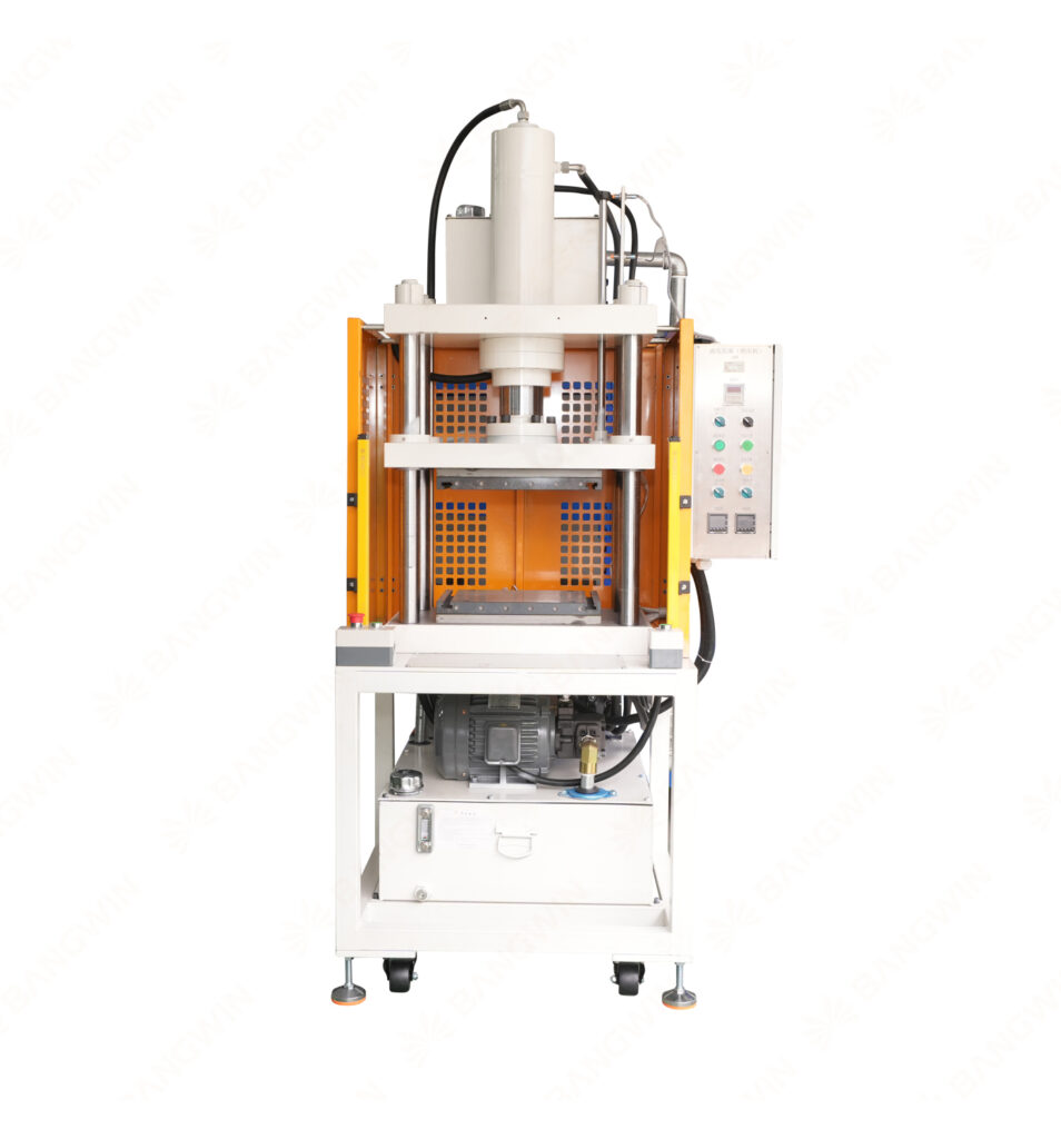
Resistance Welding Machine: Types, Uses and Benefits
1. What Is a Resistance Welding Machine?
A Resistance Welding Machine is industrial equipment that joins metal workpieces by using electrical resistance to generate heat at the joint. The process generally combines electrical current, contact resistance, and applied force.
When current passes through the workpieces, electrical resistance generates heat. The machine controls the current and force to create the required joint.
In common resistance welding processes, the electrodes also apply mechanical pressure. This pressure helps maintain contact and supports joint formation.
Unlike many arc welding processes, resistance welding usually does not require a separate filler material. However, the exact process depends on the welding method and the materials being joined.
Manufacturers use resistance welding for applications that require repeatable joints and efficient production. For example, spot welding joins overlapping sheets at localized points, while seam welding creates a series of overlapping welds along a joint.
A suitable machine must match the material, workpiece geometry, required joint strength, and production cycle.
For manufacturers comparing joining equipment, the key question is not simply whether resistance welding can join two metals. Instead, they should determine whether it can deliver the required joint quality consistently.
2. How Resistance Welding Works
Resistance welding relies on electrical heating at the contact area between metal components.
The generated heat depends on several factors, including current, electrical resistance, and the duration of current flow. This relationship illustrates why current has a strong influence on heat generation. However, actual welding behavior also depends on heat transfer, changing contact resistance, material properties, electrode geometry, and force.
A typical resistance welding cycle includes the following stages.
Step 1: Position the Workpieces
The operator or automated handling system positions the metal components between the electrodes or within the welding fixture.
Correct alignment helps establish the intended joint location. In addition, clean and consistent contact surfaces improve process stability.
Step 2: Apply Electrode Force
The machine applies a specified force to the workpieces. This force establishes contact and helps maintain the required joint conditions.
Too little force may create unstable contact or excessive local heating. Excessive force may reduce contact resistance or deform thin materials.
Therefore, engineers must optimize the force for the material and joint design.
Step 3: Apply Electrical Current
The welding transformer or power supply delivers current through the workpieces.
Electrical resistance generates heat at the contact region. Under suitable conditions, the heat creates a localized molten zone or another required joining condition.
The exact result depends on the selected resistance welding process.
Step 4: Maintain the Required Welding Cycle
The machine controls current duration and other relevant parameters. In spot welding, for example, the process may include squeeze time, weld time, hold time, and release.
The correct sequence helps control joint formation and reduce variation.
Step 5: Maintain Pressure During Cooling
In many resistance welding processes, the electrodes maintain force after current stops. This hold period allows the joint to solidify or stabilize under controlled conditions.
The appropriate timing depends on the material, welding process, and machine setup.
Step 6: Release and Inspect
The machine releases the workpiece after completing the cycle. Operators then inspect the joint according to the approved quality-control procedure.
Depending on the application, inspection may include visual examination, dimensional checks, destructive testing, or other verification methods.
3. Main Types of Resistance Welding Machines
Different resistance welding methods suit different workpiece geometries and production requirements.
3.1 Resistance Spot Welding Machine
A resistance spot welding machine joins overlapping metal sheets at localized points. Two electrodes apply force and pass current through the joint area.
The process is widely used in sheet-metal assembly and automotive manufacturing.
Spot welding can support high production rates when the component design allows suitable electrode access. However, the joint arrangement and material thickness determine the required process settings.
3.2 Resistance Seam Welding Machine
A resistance seam welding machine uses rotating wheel electrodes or a similar arrangement to create a continuous or intermittent series of welds.
This method can suit components that require a sealed or extended joint. The specific result depends on electrode movement, current control, and workpiece geometry.
Manufacturers should validate the process when the joint must meet strict leak-tightness requirements.
3.3 Projection Welding Machine
Projection welding uses designed projections or localized contact features to concentrate current and heat.
The projections help define where the weld forms. This method can support multiple welds in one cycle when the component design permits.
Projection dimensions and material consistency strongly influence the final joint quality.
3.4 Flash Butt Welding Machine
Flash butt welding joins components at their ends. The process generates heat through electrical contact and flashing before applying an upsetting force to complete the joint.
Manufacturers use this method for selected bars, rods, wires, and other compatible components.
The machine must provide suitable electrical power, movement control, and force for the workpiece dimensions.
3.5 Capacitor Discharge Resistance Welding Machine
Capacitor discharge welding releases stored electrical energy over a short period. This approach can suit certain precision joining applications.
The process may help limit the overall energy input, but the result depends on the material, component geometry, and energy settings.
Manufacturers should conduct process trials before adopting it for sensitive or thin components.
3.6 Custom Resistance Welding Systems
Some production applications require specialized electrodes, fixtures, or automated handling.
A customized resistance welding machine can accommodate particular workpiece shapes and assembly sequences. However, customization should begin with a clear understanding of the product specifications and required joint performance.
4. Key Components of a Resistance Welding Machine
Machine architecture varies by process and application. Nevertheless, several major systems influence welding performance.
4.1 Welding Power Supply
The power supply provides the electrical energy required for welding. Depending on the machine, it may use an alternating-current transformer, inverter-based power supply, or capacitor discharge system.
The power system must match the required current, duty cycle, and process-control requirements.
4.2 Electrodes
Electrodes conduct current into the workpieces and often apply mechanical force. Their material, shape, contact area, and cooling arrangement affect welding performance.
Electrode wear can change contact conditions and joint consistency. Therefore, manufacturers should establish inspection and replacement procedures.
4.3 Force Application System
The force system presses the workpieces together. Depending on the machine design, it may use pneumatic, hydraulic, servo-driven, or other mechanisms.
Stable force helps maintain consistent contact conditions. For precision applications, manufacturers should verify force repeatability.
4.4 Welding Controller
The controller manages the welding sequence and relevant parameters. Common controls include current, weld time, electrode force, and hold time.
Advanced systems may support programmable recipes, monitoring, and data recording. Available functions depend on the equipment configuration.
4.5 Cooling System
Electrodes and other components may require cooling during repeated operation. A suitable cooling system helps manage heat accumulation and supports stable production.
Manufacturers should follow the equipment supplier’s requirements for coolant quality, flow, and maintenance.
4.6 Fixtures and Workpiece Positioning
Fixtures align the components and hold them during welding. Correct positioning helps maintain the intended joint location.
A suitable fixture also supports repeatability across production batches. For thin or delicate components, it must prevent unwanted deformation.
4.7 Safety System
Resistance welding machines can involve high electrical currents, moving mechanisms, hot components, and pinch points.
Appropriate safeguards may include protective enclosures, interlocks, emergency stops, and electrical protection. The complete system should meet applicable workplace safety requirements.
5. Benefits of Resistance Welding
Resistance welding offers several potential advantages when the process matches the application.
5.1 Efficient Production
Resistance welding can complete individual joints quickly. As a result, it can suit repetitive manufacturing operations with stable workpiece geometry.
The complete production cycle still includes positioning, clamping, inspection, and handling. Manufacturers should evaluate total cycle time rather than weld time alone.
5.2 Repeatable Joint Formation
Programmable welding parameters help maintain consistent processing conditions. In addition, dedicated fixtures reduce variation caused by workpiece positioning.
However, repeatability requires regular maintenance and control of material and electrode conditions.
5.3 No Separate Filler Material in Common Processes
Conventional resistance spot and seam welding generally join compatible workpieces without a separate filler metal.
This can simplify material handling and reduce the need for additional consumables. Nevertheless, manufacturers must still account for electrodes and other operating requirements.
5.4 Automation Compatibility
Resistance welding can integrate with robotic handling, transfer systems, and automated assembly equipment.
This makes it suitable for high-volume production when the workpiece geometry and process requirements support automation.
5.5 Localized Heat Generation
Resistance welding concentrates heat near the contact area. This can reduce the need to heat the entire component.
However, localized heating can still cause indentation, distortion, or material changes. Engineers must validate the process for thin or heat-sensitive workpieces.
5.6 Adaptability to Different Applications
Different resistance welding methods serve a range of metal joining tasks. Manufacturers can select spot, seam, projection, or butt welding according to the component design.
The process must still match the materials, joint geometry, and required mechanical performance.
6. Industrial Applications
Resistance welding supports a broad range of manufacturing operations. Its suitability depends on the metal type, component structure, and required joint properties.
6.1 Automotive Manufacturing
Automotive manufacturers use resistance spot welding to join overlapping sheet-metal components. The method can support repetitive assembly and automated production.
Production requirements often include consistent weld quality, defined inspection procedures, and controlled electrode maintenance.
6.2 Electrical Components
Manufacturers use resistance welding for selected electrical contacts, terminals, connectors, and conductive assemblies.
In these applications, joint resistance and mechanical integrity may both matter. The process must avoid damage to nearby components and maintain the required electrical performance.
6.3 Sheet-Metal Fabrication
Resistance spot and seam welding can support sheet-metal assembly where the workpiece geometry provides suitable electrode access.
Manufacturers should consider surface condition, sheet thickness, overlap, and required joint strength.
6.4 Household Appliances
Certain appliance components use resistance welding to join metal parts during assembly.
The process can support repetitive manufacturing when fixtures and parameters match the product design.
6.5 Battery and Energy Components
Selected battery tabs, terminals, and conductive parts may use resistance-based joining processes. However, not every battery design suits the same welding method.
Material combinations, thickness, electrical resistance, and sensitivity to heat require careful evaluation.
6.6 Thermal Management Equipment
Thermal management products may include thin metal parts, brackets, electrical connections, and other components that require joining.
Resistance welding may suit selected applications. However, vapor chamber sealing often requires a process specifically validated for the chamber’s materials, geometry, and leak-tightness requirements.
Manufacturers should not assume that a resistance welding machine can replace a dedicated vapor chamber laser sealing machine.
7. Resistance Welding vs. Laser Welding
Resistance welding and laser welding both join metal components, but they use different energy delivery methods.
Comparison factor | Resistance welding | Laser welding |
Energy source | Electrical current and contact resistance | Concentrated laser energy |
Mechanical contact | Typically requires electrode contact and force | Usually does not require welding electrodes to contact the joint |
Access requirements | Requires suitable electrode access | Requires suitable optical access |
Typical applications | Spot, seam, projection, and selected butt joints | Narrow seams, precision joints, and complex programmed paths |
Electrode maintenance | Relevant for processes using electrodes | No welding electrodes, although optics and other parts require maintenance |
Automation potential | High for compatible repetitive operations | High for compatible programmed processing |
Thin-material considerations | Must control electrode force, current, and indentation | Must control laser energy, focus, speed, and thermal distortion |
Vapor chamber suitability | Depends on the specific joint and chamber design | Often considered for precision chamber sealing, subject to validation |
Neither method is universally superior. The right choice depends on material, geometry, required joint properties, production volume, and quality criteria.
For vapor chamber manufacturing, engineers should pay particular attention to leakage requirements and deformation risks. A process that produces a strong joint may still fail to meet the chamber’s leak-tightness requirements.
8. Important Welding Parameters
Welding performance depends on the interaction between electrical, mechanical, and material factors.
8.1 Welding Current
Current strongly affects the heat generated at the joint. Too little current may produce an insufficient weld, while excessive current can cause expulsion, excessive indentation, or other defects.
The appropriate range depends on the material, thickness, electrode geometry, and process type.
8.2 Welding Time
Welding time determines how long current flows through the workpieces.
A short cycle may not generate enough heat. An excessively long cycle may increase distortion or damage the workpiece.
Manufacturers should establish a validated process window rather than relying on a single unverified setting.
8.3 Electrode Force
Electrode force affects contact resistance and the behavior of the joint during heating.
Insufficient force may create unstable contact. Excessive force may reduce heating at the interface or deform thin materials.
Therefore, force must be optimized alongside current and time.
8.4 Electrode Geometry and Condition
Electrode shape determines the contact area and influences current distribution.
Worn or contaminated electrodes can change the welding conditions. Routine inspection and dressing or replacement, where appropriate, help maintain process consistency.
8.5 Material and Surface Condition
Material composition, thickness, coatings, and surface contamination affect resistance and heat transfer.
Manufacturers should test the actual material combination before production. They should also control incoming material variation where it affects welding quality.
8.6 Cooling Conditions
Electrode cooling can influence temperature stability during repetitive operation.
Insufficient cooling may accelerate electrode wear or change process behavior. Follow the equipment supplier’s requirements when configuring the cooling system.
9. How to Choose the Right Resistance Welding Machine
Selecting suitable equipment starts with the workpiece and production requirements.
Step 1: Identify the Welding Process
Determine whether the application requires spot welding, seam welding, projection welding, butt welding, or another resistance-based process.
The joint geometry should guide the machine type.
Step 2: Confirm Material Compatibility
Provide the supplier with material grades, thicknesses, coatings, and component drawings.
Different materials require different welding conditions. Dissimilar-metal joints may require additional feasibility testing.
Step 3: Define Joint Quality Requirements
Specify the required mechanical strength, electrical performance, appearance, or leak-tightness criteria.
The acceptance criteria should match the finished product’s intended function.
Step 4: Evaluate Power and Control Requirements
Confirm that the machine can deliver the required electrical output and control the relevant welding parameters.
For precision production, ask how the equipment monitors and maintains the process conditions.
Step 5: Review Fixtures and Electrode Access
Check whether the machine can position the workpiece and reach the required joint locations.
Custom fixtures may be necessary for complex components or repeatable automated production.
Step 6: Estimate Production Capacity
Consider welding time, workpiece loading, positioning, cooling, inspection, and unloading.
A realistic cycle-time estimate should include the entire process.
Step 7: Assess Maintenance and Operating Costs
Review electrode life, consumables, maintenance intervals, cooling requirements, energy use, and operator training.
The total cost of ownership can provide a more useful comparison than purchase price alone.
Step 8: Conduct Welding Trials
Use representative workpieces to validate the process before equipment acceptance.
Evaluate joint quality, dimensional stability, production consistency, and any required performance tests. Document the results against agreed acceptance criteria.
10. Integrating Resistance Welding into Production
A resistance welding machine can operate independently or within an automated manufacturing line.
The correct arrangement depends on workpiece geometry, production volume, and inspection requirements.
A typical workflow may include:
- Material preparation: Check component dimensions and surface conditions.
- Workpiece positioning: Load the parts into the fixture.
- Clamping: Apply the specified electrode force.
- Welding: Execute the validated current and timing sequence.
- Joint stabilization: Maintain the required hold time.
- Inspection: Evaluate the weld against defined criteria.
- Data recording: Record relevant process and inspection results.
- Downstream assembly: Transfer approved components to the next production stage.
Automation may reduce handling variation and improve production flow. However, integration requires careful coordination between the welding machine, fixtures, safety controls, and upstream and downstream equipment.
For thermal management equipment manufacturers, the production layout should also account for component cleanliness and dimensional requirements.
11. Welding Quality Control and Troubleshooting
Consistent welding quality requires more than setting current and time. Manufacturers should control materials, electrodes, fixtures, and inspection procedures.
11.1 Establish a Welding Procedure
Document the approved material combinations, electrode specifications, welding parameters, and acceptance criteria.
Operators should follow the same procedure across production shifts unless an approved change requires an update.
11.2 Inspect Weld Appearance
Visual inspection can identify certain defects, including excessive indentation, surface damage, expulsion, and inconsistent appearance.
However, visual inspection alone cannot confirm every internal weld characteristic. Additional testing may be necessary.
11.3 Verify Mechanical Performance
Depending on the application, manufacturers may use peel tests, tensile-shear tests, metallographic examination, or other suitable methods.
The selected test should reflect the joint design and applicable requirements.
11.4 Monitor Electrical Parameters
Where the machine supports monitoring, record relevant current, voltage, force, and timing data.
These records can help identify process drift. However, electrical data should be interpreted alongside actual joint quality.
11.5 Investigate Common Defects
Potential defect | Possible contributing factors | Recommended investigation |
Weak weld | Insufficient heat, poor contact, unsuitable force | Review current, time, force, and material condition |
Excessive indentation | High force, excessive heat, unsuitable electrode geometry | Check force settings, current, and electrode condition |
Expulsion | Excessive heat, unstable contact, unsuitable force | Review the process window and workpiece fit-up |
Inconsistent welds | Electrode wear, material variation, poor positioning | Inspect electrodes, fixtures, and incoming materials |
Surface damage | Contamination, electrode condition, incorrect parameters | Check surface preparation and contact conditions |
These are possible causes rather than definitive diagnoses. Manufacturers should verify the actual cause through controlled investigation.
11.6 Maintain Traceability
Production records can include product identification, machine settings, inspection results, and maintenance information.
Traceability supports defect analysis and helps manufacturers evaluate the effectiveness of corrective actions.
12. Maintenance and Operating Best Practices
Routine maintenance helps maintain process stability and reduce unexpected downtime.
Recommended practices include:
- Inspect electrodes: Check wear, contamination, alignment, and contact geometry.
- Maintain cooling systems: Follow the required coolant and flow specifications.
- Verify force control: Check that the force mechanism operates consistently.
- Review electrical connections: Inspect according to the manufacturer’s maintenance instructions.
- Check fixtures: Confirm that workpieces remain correctly positioned.
- Verify controller settings: Protect validated recipes from unauthorized changes.
- Inspect safety devices: Check interlocks, emergency stops, and other protective systems.
- Train operators: Provide training in operation, inspection, and safe handling.
- Record maintenance activities: Track repairs, adjustments, electrode replacement, and recurring defects.
When welding quality changes, review the machine condition and process records before making adjustments. This approach helps identify the cause and avoid unnecessary parameter changes.
13. Resistance Welding in Thermal Management Manufacturing
Thermal management manufacturing includes various joining and assembly operations. Depending on the product, manufacturers may need to join brackets, electrical connections, sheet-metal components, and other supporting structures.
Resistance welding can suit selected operations where the material combination, joint geometry, and quality requirements support the process.
However, vapor chambers introduce specific requirements. Their thin walls, internal structures, and sealed cavities can make joining more demanding.
For example, the process used to attach an external support component may differ from the process used to seal the chamber itself. The former may suit resistance welding, while the latter may require a validated laser sealing or another suitable joining process.
Manufacturers should therefore assess each joint separately.
When evaluating equipment for vapor chamber production, consider:
- Material thickness and composition
- Joint location and accessibility
- Permitted deformation
- Required mechanical strength
- Leak-tightness requirements
- Thermal performance requirements
- Production throughput and inspection needs
cncoolingthermal focuses on equipment related to vapor chamber and thermal management manufacturing. Visit https://cncoolingthermal.com/ to explore relevant equipment categories and identify solutions for your production process.
14. Frequently Asked Questions
Q1. What does a resistance welding machine do?
A resistance welding machine joins compatible metal components by generating heat through electrical resistance at the joint. The process generally combines electrical current with mechanical force.
Q2. What are the main types of resistance welding?
Common types include resistance spot welding, seam welding, projection welding, and flash butt welding. The suitable method depends on workpiece geometry and joint requirements.
Q3. Does resistance welding require filler metal?
Conventional resistance spot and seam welding generally do not require separate filler metal. However, requirements vary by process and application.
Q4. Which materials can a resistance welding machine join?
Resistance welding can join various conductive metals, but compatibility depends on material composition, thickness, surface condition, and joint design.
Manufacturers should validate the selected process using representative workpieces.
Q5. What affects resistance welding quality?
Important factors include welding current, time, electrode force, electrode geometry, material condition, and workpiece alignment.
Consistent maintenance and process monitoring help reduce variation.
Q6. Is resistance welding suitable for thin metal sheets?
It can be suitable for certain thin-sheet applications. However, engineers must control heat input and electrode force to prevent excessive indentation, expulsion, or deformation.
Q7. What is the difference between resistance welding and laser welding?
Resistance welding generates heat through electrical resistance at the contact area. Laser welding uses concentrated optical energy to heat and join the material.
The appropriate method depends on the joint, materials, production requirements, and quality criteria.
Q8. Can resistance welding be automated?
Yes. Suitable machines can integrate with robotic handling, automatic fixtures, transfer systems, and production monitoring.
The integration design should account for workpiece geometry, cycle time, and safety requirements.
Q9. Can a resistance welding machine seal vapor chambers?
That depends on the chamber structure and required sealing performance. Manufacturers should not assume that conventional resistance welding can replace a dedicated vapor chamber sealing process.
Any proposed method requires validation against the chamber’s leak-tightness, dimensional, and reliability requirements.
Q10. How can manufacturers choose the right machine?
Start with the material specifications, joint geometry, required quality, and production volume. Then compare machine capability, process control, fixture design, maintenance needs, and validation results.
Representative welding trials can help confirm whether the equipment suits the application.
15. Conclusion
A Resistance Welding Machine provides an effective metal-joining solution for suitable industrial applications. By controlling electrical current, welding time, and mechanical force, manufacturers can produce repeatable joints and integrate the process into automated production.
However, successful welding requires the correct process selection, compatible materials, stable fixtures, and effective quality control. Electrode condition and parameter stability also influence the final result.
For thermal management manufacturing, resistance welding may suit selected component assembly tasks. Nevertheless, manufacturers must evaluate vapor chamber sealing separately because thin structures and leak-tightness requirements can demand specialized joining methods.
cncoolingthermal provides a starting point for exploring vapor chamber and thermal management manufacturing equipment. Visit cncoolingthermal.com to learn more about related production solutions.