
Product Description
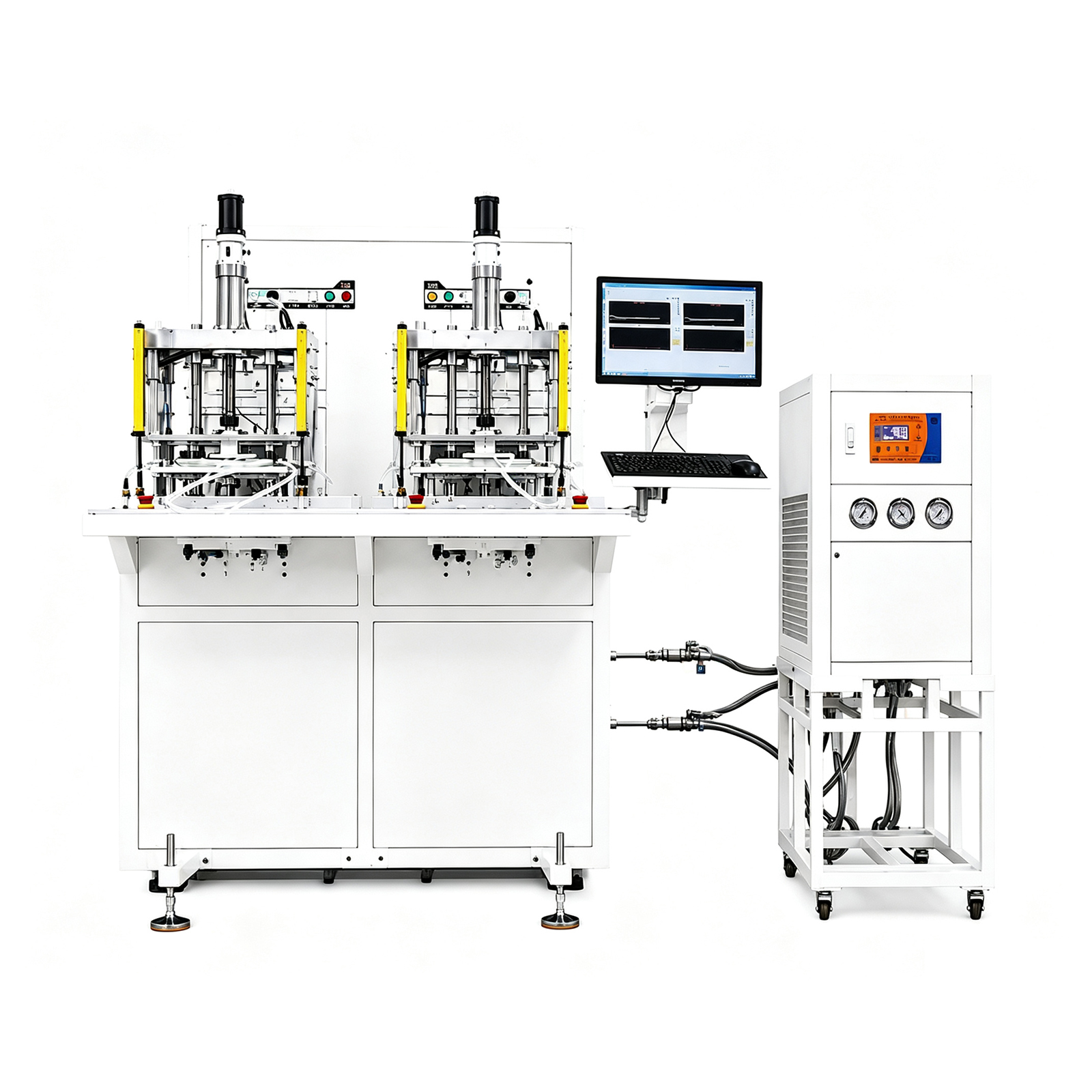
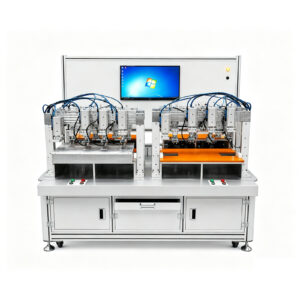
Cold Plate Flow Resistance Test Machine
In a liquid-cooled rack, the pump in the Coolant Distribution Unit (CDU) has a fixed pressure budget. If even one cold plate has higher flow resistance than its design specification, the entire loop drops below its target flow rate. The result is thermal throttling, or worse, a CPU/GPU shutdown.
Hyperscale customers now specify pressure-drop tolerance bands as tight as ±10% of design target. As a public reference, the NVIDIA GB200 GPU cold plate is validated at 35 kPa ± 3.5 kPa at 2.5 LPM, and the AMD SP5 CPU cold plate at under 3 kPa at 1 LPM [1]. Production cold plates have to hit those numbers, every unit, every shift.
The CT-FRT-30 Flow Resistance Test Machine is built for that job. It runs a controlled flow rate through the part under test, measures the differential pressure across the inlet and outlet, and automatically generates the full ΔP-Q curve across the design operating range. Standard configuration handles flow rates from 0.5 to 30 LPM, with extension options up to 60 LPM for larger battery cold plates and CDU manifolds.
Key Features
• Automated ΔP-Q curve generation — set the flow points once in a recipe, the system steps through each point, stabilizes, measures, and plots the full curve
• Wide flow rate range (0.5 – 30 LPM standard) — covers everything from microchannel GPU cold plates to power electronics plates on one machine
• High-accuracy differential pressure measurement (±0.5% FS) with auto-zero before each test cycle
• Closed-loop temperature control (5 – 70°C) — fluid viscosity changes with temperature, so isothermal testing is essential for reliable comparison against design data
• Variable-speed magnetic-drive pump — no shaft seal means no leak risk and minimal maintenance
• Pass/fail decision per recipe — automatic comparison against design ΔP target with adjustable tolerance band
• Full traceability — every test result logged with part ID, test conditions, raw data, and curve; exportable as CSV and PDF report
• Modular fixture design — quick-connect couplings adapt to G1/4, G3/8, OD8/10 tubing, and standard server cold plate manifold interfaces
• Optional helium leak test integration — combine hydraulic test and leak test in one station to save factory floor space
• Compact single-operator footprint
Technical Specifications
| Parameter | Value |
| Model | CT-FRT-30 |
| Test type | Hydraulic flow resistance / pressure drop characterization |
| Flow rate range | 0.5 – 30 LPM (extendable to 60 LPM) |
| Flow measurement accuracy | ±0.5% of reading (electromagnetic flow meter) |
| Differential pressure range | 0 – 200 kPa (other ranges on request) |
| Pressure measurement accuracy | ±0.5% FS |
| Inlet/outlet temperature sensors | Pt100 RTD, ±0.1°C |
| Coolant temperature control | 5 – 70°C, ±0.5°C (with integrated chiller) |
| Pump | Variable-speed magnetic-drive pump (no shaft seal, leak-free) |
| Test fluid (standard) | Deionized water; ethylene glycol / water mixtures supported |
| Test recipe automation | Auto ΔP-Q curve, 3–20 flow points programmable |
| Data acquisition | 8–16 channels, 10 Hz sampling, real-time graphing |
| Control system | PLC + 15″ HMI touchscreen + PC software |
| Data output | CSV, PDF report, Ethernet, optional MES integration |
| Power supply | 380V / 50Hz / 3-phase (220V single-phase available) |
| Total power | 5 kW (including chiller) |
| Machine dimensions (L×W×H) | 1800 × 1000 × 1800 mm (typical, configurable) |
| Machine weight | ~ 500 kg |
| Compliance | CE-ready design |
Note: parameters above are typical for the standard 30-LPM configuration. Custom configurations available for higher flow rates (up to 200+ LPM for CDU manifold testing), alternative test fluids, or integrated thermal performance measurement.
How It Works: ΔP-Q Curve Characterization
The flow resistance of a cold plate is fully described by a single curve: differential pressure (ΔP) as a function of volumetric flow rate (Q). This curve is the contract between the cold plate and the CDU pump. If the actual curve sits above the design curve, the cold plate is too restrictive and the loop will run short on flow. If it sits below, the curve still has to be characterized so the system designer can plan the pump operating point.
The test cycle has five phases:
1. Mount and fill — the part is connected to the test manifold via quick-connect couplings; the loop is flushed and purged of air (air bubbles destroy ΔP accuracy)
2. Temperature stabilize — the chiller brings the fluid to the recipe set point (typically 25°C or 40°C); viscosity is held constant during the test
3. Step through flow points — the pump speed is stepped through the programmed flow rates (typical: 5 points spanning 50% to 150% of design flow)
4. Measure and record — at each flow point, the system waits for ΔP to stabilize, then records flow, pressure, and temperature over a fixed averaging window
5. Curve fit and decision — the system fits the data, plots the curve against the design target, and assigns pass or fail based on the recipe tolerance band
For background on why pressure drop is now a first-class design constraint in AI data center cooling, see this overview from JetCool on flow, pressure, and infrastructure in liquid cooling system design.
Reference Cold Plate Benchmarks
Public-domain validation data for current-generation cold plates, useful for sizing your test machine flow range:
| Cold Plate Type | Design Flow | Pressure Drop | Source |
| NVIDIA GB200 GPU cold plate | 2.5 LPM | 35 kPa ± 3.5 kPa | ToneCooling |
| AMD SP5 CPU cold plate | 1.0 LPM | < 3 kPa | ToneCooling |
| Microchannel AI cold plate (typical) | 1.5 – 2 LPM | 20 – 60 kPa | Industry typical |
| Power electronics cold plate | 10 LPM | 30 – 400 mbar | Aerospace patent |
Note: the GB200 figure is the publicly disclosed validation point; the AMD SP5 figure reflects a low-power CPU cold plate. Power electronics and EV battery cold plates typically need higher flow capacity and a wider pressure range — discuss the actual part family with us when configuring the machine.
Applications
AI Server & GPU Cold Plates
NVIDIA H100, GB200, AMD MI300, and similar high-power accelerator cold plates have very tight ΔP windows because rack-level CDU pump budgets are also tight. ΔP-Q characterization is now a mandatory production test, not an R&D-only step.
CPU Cold Plates
Server CPU cold plates (SP5, SP3, LGA 4677, etc.) usually run at lower flow rates and lower ΔP than GPU plates, but the same principle applies — the plate has to match the pump curve.
EV Battery Liquid Cooling Plates
Battery cooling plates carry the highest flow rates in the system, typically 5 – 30 LPM per pack zone. Flow imbalance between zones translates directly into temperature imbalance between cells, which shortens pack life. Flow resistance testing verifies both the absolute ΔP and the balance across multiple ports.
Power Electronics & IGBT Cold Plates
Inverter, traction motor controller, and laser power supply cold plates often use ethylene glycol mixtures with viscosity 3 – 5x higher than water. The test machine supports glycol fluids and reports ΔP at the actual production fluid, not just water-equivalent.
CDU Manifolds and Quick Disconnects
Manifolds, quick disconnects, and bend fittings each contribute to the rack-level pressure budget. Characterizing them individually lets system designers stack the curves and predict actual rack flow with confidence.
Why Choose Cooling Thermal
• Built for production, not just R&D — most commercial flow benches are lab instruments; ours is designed for daily production use, with cycle times under 3 minutes per part
• Real cold plate experience — we build production equipment for cold plate, heat pipe, and vapor chamber manufacturers across Korea, Vietnam, Thailand, and India, so we know what the production line actually needs
• Custom flow ranges and fluids — we can extend the flow range or add specialty fluid handling without redesigning the whole machine
• Combined-test option — flow resistance + leak test in one station saves floor space and reduces the number of part handlings
• Engineer-led commissioning — on-site installation, operator training, and process tuning included as standard
This machine integrates naturally into our broader thermal manufacturing equipment lineup, which covers production from raw stock through final test for cold plates, heat pipes, and vapor chambers.
How The Cold Plate Flow Resistance Test Machine Works

Cold Plate Loading & Fixture Mounting

Loop Filling & Air Purge

Thermal Stabilization

Reviews
There are no reviews yet.