
Product Description
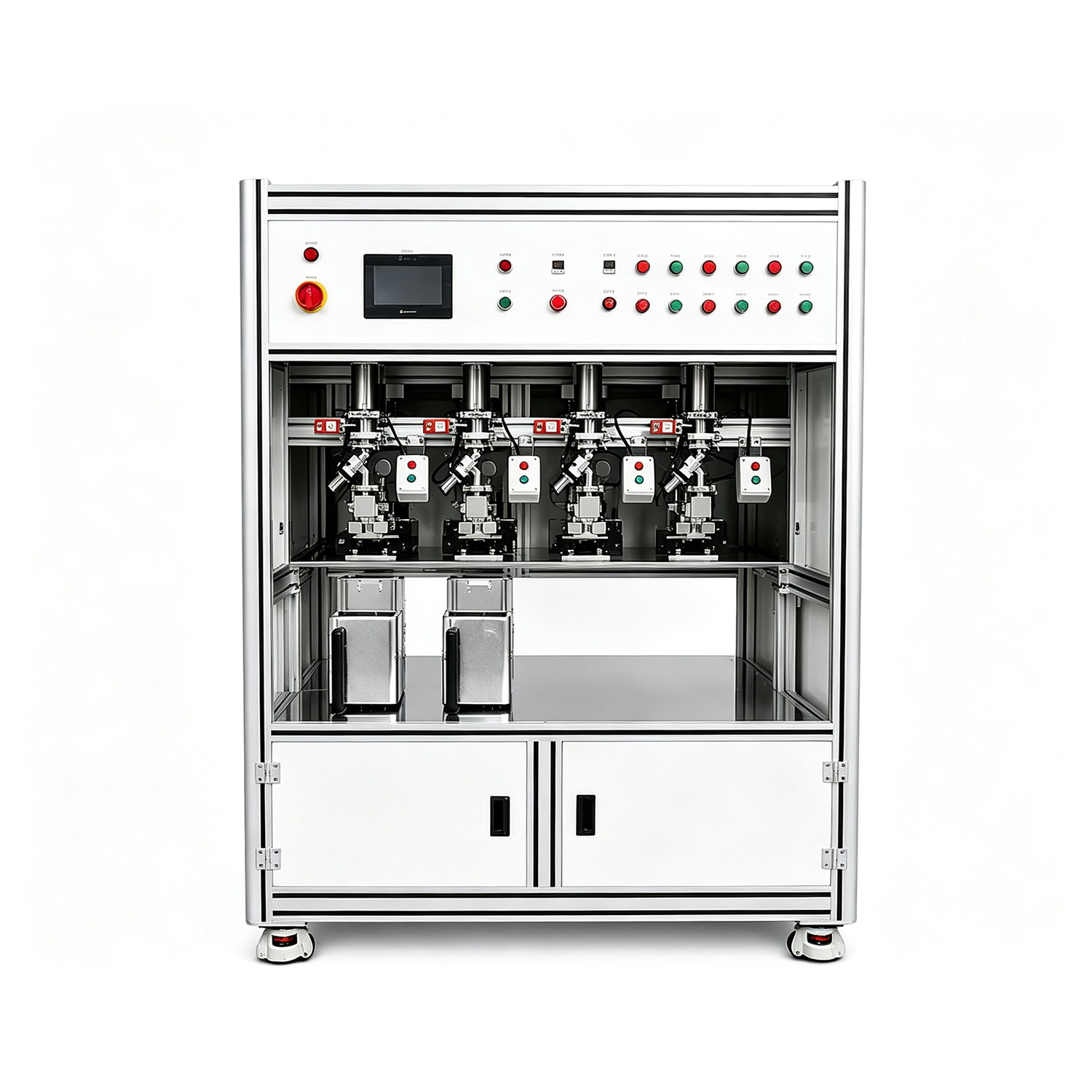
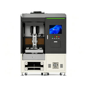
Thermal Performance Testing Machine for Heat Sink and Heat Pipe Testing — Automated Thermal Resistance Measurement, Cooling Capacity Verification & Data Logging
A thermal performance testing machine is automated test equipment that measures heat sink and heat pipe thermal resistance, cooling capacity, and temperature distribution under controlled heat load conditions. The machine applies a calibrated heat source (programmable from 150W to 1200W), monitors multiple temperature points simultaneously (4–20 thermocouples), and calculates thermal resistance (°C/W) in real-time — enabling manufacturers to verify thermal performance against specifications before shipping to customers. This quality assurance step is critical because heat sink failures in the field (GPU throttling, CPU overheating, IGBT module failure) are often traced to inadequate thermal resistance testing during production.
Why Manufacturers Choose Our Thermal Performance Testing Machine
1.Programmable Heat Source with Wide Power Range (150W–1200W)
The machine’s programmable heat source spans 150W to 1200W in 1W increments, covering thermal testing requirements from low-power LED heat sinks (30–100W) through high-performance GPU / AI accelerator cooling modules (500W–1200W). Unlike fixed-wattage heater systems that require hardware changes to test different products, our software-controlled power supply adjusts output instantly via touchscreen interface. Heat load ramps up smoothly to prevent thermal shock, holds steady-state for accurate resistance measurement, and ramps down gradually during cooldown — protecting both the test sample and the heating element from thermal cycling damage. This flexibility eliminates the need to purchase multiple test machines for different product lines, reducing capital investment by 60–70% for manufacturers producing both low-power consumer and high-power data center thermal solutions.
2.Multi-Channel Temperature Sensing (4–20 Sensors)
Standard configuration supports 4–8 thermocouple channels; optional upgrade extends to 12–20 channels for complex multi-die modules or large-area vapor chambers. Each channel is independently sampled at 1Hz with ±0.3°C accuracy, enabling precise junction temperature mapping across the entire heat source surface. The system automatically identifies the hottest sensor (Tmax), calculates thermal resistance (Rth = (Tmax – Tambient) / Power), and flags any sensor reading that exceeds the specified temperature limit — triggering an immediate test abort to prevent sample damage. For heat pipes, the multi-channel array measures evaporator-to-condenser temperature gradient, verifying that the working fluid is circulating properly. For vapor chambers, the sensor array maps temperature uniformity across the spreading surface, identifying localized hot spots that indicate manufacturing defects (inadequate capillary structure, trapped air, or incomplete fluid charge).
3.Automated Test Cycle Control with PWM Fan Speed Management
The machine automates the entire thermal test sequence: (1) operator loads heat sink and mounts thermocouples, (2) machine verifies thermocouple contact (resistance check), (3) heat source ramps to target power, (4) system monitors temperature stabilization (steady-state detection: <0.2°C change over 60 seconds), (5) thermal resistance calculated and logged, (6) heat source powers down and optional cooling fan accelerates for rapid cooldown. The integrated PWM fan controller adjusts airflow from 0% to 100% in real-time, enabling both natural convection testing (fan off) and forced convection testing (fan speed controlled to maintain specified airflow velocity). This eliminates manual intervention — operators simply load samples and start tests; the machine handles everything else. Throughput increases from 5–8 manual tests per hour to 12–18 automated tests per hour, directly reducing labor cost and improving test consistency.
4.Real-Time Data Logging and Thermal Resistance Calculation
Every test generates a complete data record: test sample ID (barcode scanner optional), heat source power, all temperature sensor readings (logged every 1 second), calculated thermal resistance, ambient temperature, fan speed (if applicable), test duration, and pass/fail status. Data exports to CSV format for analysis in Excel, imports into MES/ERP systems via Ethernet or USB, and archives on the machine’s internal SD card for regulatory compliance (AS9100 aerospace, IATF 16949 automotive). The system displays real-time temperature curves on the touchscreen during testing, allowing operators to visually confirm steady-state behavior and identify anomalous thermal transients. For quality assurance departments, this traceability is essential — every shipped heat sink has a permanently linked thermal test record proving it met specifications.
5.Versatile Fixture Design for Heat Sinks, Heat Pipes, and Modules
The test fixture accommodates a wide range of thermal product form factors: CPU/GPU heat sinks (square, rectangular, tower-style), heat pipe assemblies (flat, sintered, grooved), vapor chambers (ultra-thin to thick), IGBT power modules (press-fit, bolt-down), and LED COB arrays. Quick-change mounting plates allow fixture reconfiguration in <5 minutes without tools — simply swap the mounting plate, adjust thermocouple positions, and start testing. This versatility eliminates the need for custom test equipment for each product line. The heated contact surface is precision-machined flat (±0.01mm) and coated with thermal interface material to ensure uniform heat transfer into the test sample, preventing localized hot spots that would distort thermal resistance measurements.
Technical Specifications
| Specification | Details |
| Voltage | AC 220V / 380V (configurable) |
| Power Consumption | 2–4 kW (depending on heat source power setting) |
| Heat Source Power Range | 150W – 1200W (programmable in 1W increments) |
| Heat Source Type | Resistive heating element with PID temperature control |
| Heating Surface Size | 50 × 50mm standard (customizable to 100 × 100mm) |
| Temperature Sensor Channels | 4–8 channels standard, expandable to 12–20 channels |
| Sensor Type | K-type thermocouples (standard), T-type or PT100 optional |
| Temperature Accuracy | ±0.3°C (K-type), ±0.1°C (PT100) |
| Sampling Rate | 1 Hz (1 sample per second, all channels simultaneously) |
| Thermal Resistance Range | 0.01 – 5.0 °C/W (calculable) |
| Ambient Temperature Monitoring | Dedicated ambient sensor with ±0.5°C accuracy |
| Fan Speed Control | PWM 0–100%, supports 3-pin / 4-pin PWM fans |
| Airflow Measurement | Optional anemometer for forced convection testing |
| Test Fixture Compatibility | CPU/GPU heat sinks, heat pipes, vapor chambers, IGBT modules, LED COBs |
| Fixture Mounting | Quick-change plate system, <5 min reconfiguration |
| Control System | PLC + 7-inch color touchscreen, parameter storage & recall |
| Test Automation | Automated heat ramp, steady-state detection, cooldown, data export |
| Steady-State Detection | Auto-detect when temperature change <0.2°C over 60 seconds |
| Data Logging | CSV export via USB/Ethernet, internal SD card archive |
| Barcode Scanner | Optional — links test data to product serial number |
| MES/ERP Integration | Ethernet TCP/IP, Modbus RTU/TCP protocols |
| Safety Features | Over-temperature cutoff, emergency stop button, heater timeout protection |
| Production Throughput | 12–18 tests per hour (automated), 17–20 tests per shift typical |
| Machine Dimensions | 800 × 700 × 1,400 mm (W × D × H) |
| Machine Weight | 120 kg |
| Operating Environment | 15–30°C ambient, <80% humidity, dust-free recommended |
Where the Thermal Testing Machine Fits in Your Production Line
The thermal performance testing machine is positioned as the final quality gate before heat sinks and heat pipe assemblies ship to customers. It is the last verification step that confirms every thermal product meets thermal resistance specifications.
In a typical thermal solution production line, the process flow is:
Heat Sink Fin Machining → Base Plate Machining → Heat Pipe Insertion (if applicable) → Soldering/Brazing → Visual Inspection → Thermal Performance Testing (THIS MACHINE) → Final Packaging & Shipping
For heat pipe manufacturers, the test comes after sealing and charging:
Tube Cutting → Capillary Structure Insertion → Tube Shrinking → Degassing & Fluid Injection → Sealing → Thermal Performance Testing (THIS MACHINE) → Quality Certification → Shipping
The thermal testing machine sits at the final step before customer shipment. A heat sink that looks perfect visually can still fail thermally due to poor base flatness, inadequate heat pipe contact, insufficient thermal interface material, or manufacturing defects in the capillary structure. The thermal test catches these hidden failures before they reach customers — preventing costly field returns, warranty claims, and reputation damage.
CoolingThermal supplies complete production equipment for heat sinks, heat pipes, and vapor chambers. The thermal testing machine can be ordered standalone to upgrade your existing quality control process, or integrated with our [heat sink production equipment] and [heat pipe manufacturing machines] as a complete turnkey production line.
How the Thermal Performance Testing Machine Works

Test Sample Mounting

Thermocouple Placement

Heat Source Application

Thermal Steady

Reviews
There are no reviews yet.