
Product Description
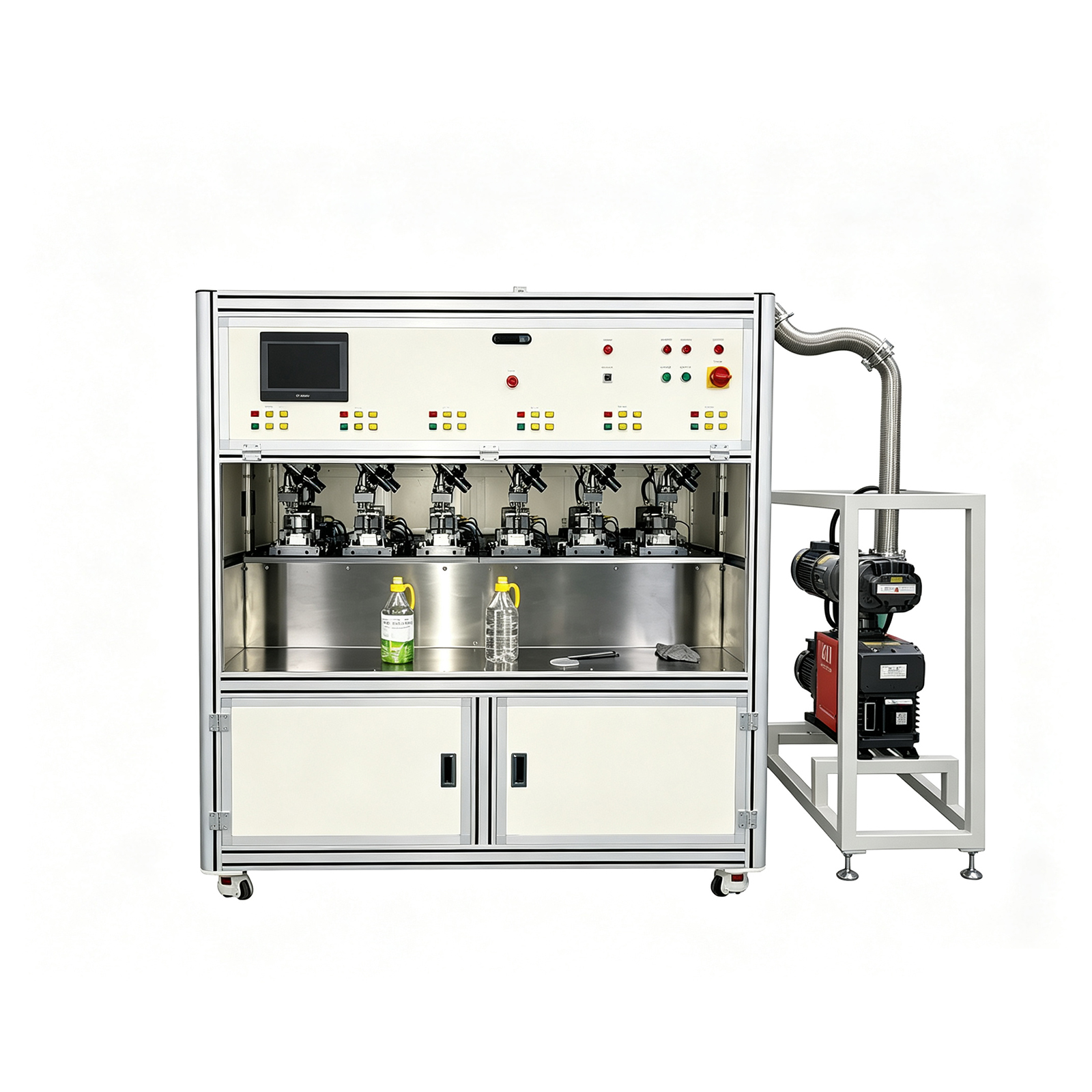
Unlike heat pipe degassing — where the degassing end geometry provides a defined port for the vacuum pump connection — vapor chamber degassing must evacuate the entire flat panel cavity through the VC’s fill port, managing the vapor pressure of the working fluid (typically ultra-pure water) at the evacuation temperature to achieve a complete non-condensable gas removal without removing the working fluid itself. This is technically more demanding than heat pipe degassing and requires a vacuum system specifically calibrated for the working fluid vapor pressure at the VC’s operating temperature. Cooling-Thermal’s vapor chamber degassing machine incorporates this calibrated vacuum system design — not the general-purpose vacuum pump approach used in non-VC-specific industrial degassing equipment.
Key Specifications & Model Overview
| Specification | Value |
| Primary Function | Vacuum pump evacuation of vapor chamber + sealing and welding in one automated cycle |
| Non-Condensable Gas Removal | Complete evacuation via vacuum pump system |
| Process Integration | Degassing + vacuum sealing + welding — single machine |
| Product Type | Vapor chamber (VC) flat thermal spreaders |
| Automation | Automatic vacuum cycle — pump, seal, weld |
| Control System | Vacuum pump system with integrated control |
| Application | VC production line — between working fluid injection and final testing |
| Manufacturer | Cooling-Thermal Co., Ltd. |
| OEM/ODM | Available |
Three-Model Overview
| Model | Standard VC Degassing Machine | VC Vacuum Welding Machine | Ultra-Thin VC Degassing Machine |
| Primary process | First degassing + vacuum sealing | Secondary degassing + precision welding | Ultra-thin VC degassing |
| Vacuum function | Vacuum pump evacuation + sealing | Vacuum pump evacuation + sealing | Vacuum pump evacuation |
| Target product | Standard thickness | Standard VC requiring secondary degassing | Ultra-thin VC (laptop, mobile) |
| Position in VC line | Post working-fluid injection | Post primary sealing | Per ultra-thin VC process |
| OEM/ODM | Available | Available | Available |
What Is Vapor Chamber Degassing — Why Non-Condensable Gas Removal Is the Most Critical Step in VC Manufacturing
A vapor chamber functions through the continuous evaporation, transport, and condensation of a working fluid (ultra-pure water) within a sealed flat copper cavity. The working fluid evaporates at the heat source, the vapor travels across the VC cavity to the condenser region, condenses back to liquid, and is returned to the evaporator by the capillary wick structure. This phase-change cycle operates under the vapor pressure of the working fluid — which, for water, is approximately 3.2 kPa at 25°C. For the cycle to function, the internal pressure of the vapor chamber must be equal to or lower than this vapor pressure: any non-condensable gas (NCG) present inside the sealed VC adds to the internal pressure beyond the working fluid vapor pressure, reducing the effective partial pressure available for evaporation, suppressing the phase-change cycle, and degrading thermal performance.
The relationship between NCG content and VC thermal performance is not linear — even trace quantities of non-condensable gas cause measurable thermal resistance increase. A vapor chamber that degasses to 99% NCG removal still contains enough residual gas to cause 5-15% thermal resistance increase compared to a fully degassed VC at operating temperature. In high-performance thermal solutions for AI servers, data centre CPUs, and mobile processors where the VC is operating near its thermal design power limit, this residual NCG thermal resistance degradation is the difference between a passing and a failing unit at the performance test station.
Vapor chamber degassing is technically more demanding than heat pipe degassing for three reasons. First, the VC’s flat cavity geometry has a much larger internal volume-to-port-area ratio than a cylindrical heat pipe — evacuation takes longer and requires a vacuum system with sufficient pumping speed for the cavity volume. Second, the thin copper walls of the VC panel (typically 0.2-0.8mm) are more susceptible to deformation under differential pressure during evacuation, requiring controlled ramp-down of pressure to avoid panel distortion that would affect the internal wick structure. Third, the working fluid must remain inside the VC during evacuation — the vacuum system must manage evacuation at a temperature and pressure where the working fluid stays in liquid phase, not above its boiling point at the evacuation pressure.
Complete non-condensable gas removal — not just partial degassing — is the quality standard for vapor chambers in AI server, data centre, and high-performance mobile thermal solutions. The degassing machine either achieves it or the VC fails at performance test.
Three-Model Range — Standard VC Degassing, Secondary Degassing & Welding, and Ultra-Thin VC Degassing
Model 1 — Standard Vapor Chamber Degassing Machine
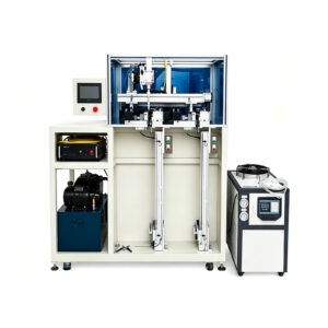
The standard Vapor Chamber Degassing Machine performs the primary evacuation and sealing cycle for standard-thickness vapor chamber panels. Using the vacuum pump system to evacuate the VC cavity through the fill port, it removes non-condensable gases and closes the evacuation port in a single automated sequence — preventing atmospheric air re-entry between the degassing and sealing steps. This is the production workhorse model for the majority of VC production applications: CPU cooler vapor chambers, server rack thermal spreaders, and standard-format GPU cooling VCs. The machine is designed to integrate into the VC production line at the post-working-fluid-injection, pre-final-testing position.
Model 2 — Vapor Chamber Vacuum Welding Machine (Secondary Degassing)
Some vapor chamber designs — particularly those with complex internal wick structures, larger cavity volumes, or demanding non-condensable gas specifications for high-performance AI server and data centre applications — require a two-stage degassing process. The standard model performs the primary evacuation and temporary sealing; the Vapor Chamber Vacuum Welding Machine then performs a secondary evacuation cycle on the already-sealed VC to extract any NCG that remained after the first pass, followed by a precision welding operation that permanently closes the VC seam under vacuum. Two-stage degassing consistently achieves lower residual NCG levels than single-stage degassing for demanding VC specifications — and the combination of vacuum environment welding with the secondary degassing step ensures the weld seam does not introduce atmospheric contamination during the closing operation.
Model 3 — Ultra-Thin Vapor Chamber Degassing Machine
Ultra-thin vapor chambers — used in laptop thermal modules, smartphone cooling layers, and tablet thermal spreaders — present unique degassing challenges compared to standard-thickness VC panels: thinner walls (as little as 0.2mm copper) require much more controlled pressure ramp-down during evacuation to prevent panel distortion; the smaller internal cavity volume means faster pressure change per pump stroke, requiring more precise vacuum control; and the fill port geometry is typically smaller, requiring higher vacuum system pumping efficiency per unit port area. Cooling-Thermal’s Ultra-Thin Vapor Chamber Degassing Machine is specifically configured for these requirements — with evacuation speed and pressure control parameters matched to ultra-thin VC specifications — rather than being a standard VC degassing machine adapted for thinner panels.
Vapor Chamber Applications & Degassing Machine Model Selection
| VC Application | VC Type | Recommended Model | Key Degassing Requirement |
| CPU & GPU coolers | Standard thickness 2-4mm copper VC | Standard VC Degassing Machine | Complete NCG removal — standard thermal specification |
| AI server thermal spreaders | Large-format, high-power | Standard + Secondary (2-stage) | Ultra-low NCG — near TDP limit operation |
| Data centre cold plates | Complex internal structure VC | Secondary Degassing Machine | Two-stage for complex wick structure |
| Laptop thermal modules | Ultra-thin 0.4-0.8mm VC | Ultra-Thin VC Degassing Machine | Controlled thin-wall pressure ramp |
| Smartphone cooling | Ultra-thin 0.2-0.4mm VC | Ultra-Thin VC Degassing Machine | Ultra-thin wall — no deformation |
| EV power electronics | Custom OD VC, ruggedized | OEM specification | Custom vacuum profile — OEM process |
If your vapor chamber specification — including panel dimensions, copper wall thickness, working fluid type, internal wick geometry, or non-condensable gas performance target — falls outside the standard model application range, contact Cooling-Thermal’s engineering team. As a specialist thermal solution automation manufacturer with direct VC production line experience, our engineers can specify the correct vacuum system configuration and process parameters for your VC design.
VC Production Line Position — Where Vapor Chamber Degassing Fits in the Manufacturing Sequence
The vapor chamber degassing machine is positioned in the VC production sequence after working fluid injection and before final performance testing. It is the last process step that determines the internal vacuum quality of the finished VC — and therefore the last step at which a non-conforming unit can be identified and rejected before it completes the entire production process.
| VC Production Step | Equipment |
| Copper column placement | Copper Column Display Machine (X-Y positioning, vibrating tray) |
| Resistance welding | Continuous Resistance Welding Machine |
| Working fluid injection | Working fluid filling system |
| Primary degassing & sealing | Vapor Chamber Degassing Machine |
| Secondary degassing & welding | Vapor Chamber Vacuum Welding Machine |
| Final testing | Automatic Performance Testing Machine (VC mode) |
Why degassing must occur after working fluid injection and before final sealing: The working fluid (ultra-pure water) must be present inside the VC during degassing, because the degassing process uses the vapor pressure of the working fluid as the reference point for determining when non-condensable gas removal is complete. Degassing before working fluid injection would remove the reference vapor pressure entirely, making it impossible to distinguish complete NCG removal from simple over-evacuation that damages the wick structure. Degassing after final sealing would require reopening the sealed VC — which destroys the assembly and contaminates the internal environment.
Vapor Chamber Degassing vs Heat Pipe Degassing — Why VC Requires Different Equipment
B2B procurement teams evaluating vapor chamber degassing machines sometimes ask whether a heat pipe degassing machine can be adapted for VC production. The answer is no — and understanding the technical differences explains why Cooling-Thermal offers dedicated VC degassing equipment rather than configuring a heat pipe machine for VC use.
| Parameter | Heat Pipe Degassing | Vapor Chamber Degassing |
| Product geometry | Cylindrical tube — defined port at one end | Flat panel — fill port in specific location |
| Cavity volume | Small — single tube OD × length | Large — full VC panel area × thickness |
| Wall thickness | 0.08-1.0mm | 0.2-0.8mm — deformation risk higher |
| Evacuation speed requirement | Moderate — small volume | High — large flat cavity |
| Pressure ramp-down control | Standard controlled | Critical — thin flat wall risk |
| Working fluid management | Inject then degas | Degas while fluid present |
| Seal method | Crimp-weld at tube neck | Flat seam weld at fill port |
| Seal geometry | Cylindrical crimp — simple | Flat panel fill port — precision weld |
| Two-stage process | Rare — single-stage standard | Common for demanding specs |
| Equipment compatibility | Not compatible with VC flat geometry | Purpose-built for flat VC panels |
Why Choose Cooling-Thermal— Competitive Advantages for B2B Procurement of VC Degassing Equipment
| Cooling-Thermal VC Degassing Machine | General Vacuum Degassing Equipment | |
| Application specificity | Designed exclusively for vapor chamber flat VC geometry | General-purpose: resins, rubber, food, pharmaceuticals |
| Process integration | Degassing + sealing + welding in one cycle | Degassing only — no sealing or welding function |
| Vacuum system | Calibrated for VC working fluid vapor pressure | Standard vacuum — not calibrated for VC working fluid |
| Product geometry handling | Flat VC panel clamping and sealing fixtures | Cylindrical or batch container — incompatible with flat VC |
| Secondary degassing | Dedicated VC secondary degassing machine available | Single-pass only — no secondary degassing configuration |
| Ultra-thin VC capability | Ultra-thin VC dedicated model available | Not applicable |
| VC line integration | Designed as part of complete VC production line | Standalone only — no VC line context |
| Client validation | Foxconn, Nidec, Furukawa, Cooler Master | General industrial customers |
| OEM/ODM | Available for VC-specific process requirements | Standard configurations only |
| After-sales | 5-person in-house specialist team | Limited or third-party |
Cooling-Thermal’s vapor chamber degassing machines are validated components of complete VC production lines delivered to Foxconn, Nidec (20 lines), Furukawa Electric, and Cooler Master. The VC thermal solution production standards at these manufacturers define the benchmark for non-condensable gas removal quality, vacuum sealing integrity, and production throughput that B2B buyers in the AI server cooling, data centre, and consumer electronics thermal solution markets expect from production-grade VC manufacturing equipment. Our machines meet these benchmarks because they were specified and validated against them — not adapted from general industrial vacuum equipment.
Delivery, Installation & After-Sales Support — Vapor Chamber Degassing Machine Service
Factory Acceptance Test (FAT)
Every machine undergoes a full FAT at our Kunshan facility: vacuum system performance against your VC specifications (panel dimensions, wall thickness, working fluid type), evacuation cycle verification, sealing and welding function test, pressure stability verification (NCG check), and integration interface testing if supplied as part of a complete VC line. FAT attendance in person or via live video is welcome.
On-Site Installation & Commissioning
Our engineers travel to your facility for installation: vacuum system setup for your VC working fluid and panel geometry, evacuation process calibration, sealing and welding parameter setup, production trial runs, and operator qualification. Commissioning is complete when the machine consistently achieves the specified NCG removal target and seal integrity on your actual VC panels.
Operator Training
Training covers: vacuum system operation and parameter management, pressure ramp-down profile setup for your VC specifications, NCG verification procedure, sealing and welding cycle operation, pressure stability failure diagnosis, and preventive maintenance. Full English technical documentation provided.
Long-Term Maintenance
5-person in-house maintenance team: vacuum pump servicing, valve and seal inspection, vacuum system leak-down testing, welding electrode maintenance, and periodic NCG verification re-qualification. Maintaining vacuum system performance is essential for sustained VC quality — our team provides scheduled preventive maintenance to ensure the degassing quality standard is maintained over the equipment’s production lifetime.
Export
FOB, CIF, DDP. Exported to Japan, South Korea, India, Turkey, Vietnam, Taiwan. Full export documentation provided.
Complete Your Vapor Chamber Production Line — VC Equipment from a Single-Source Specialist Manufacturer
Cooling-Thermal supplies all equipment required for complete vapor chamber production lines as a single-source specialist thermal solution automation manufacturer. The vapor chamber degassing machine is one station in a production sequence that includes: copper column display and placement (vibrating tray, X-Y positioning), continuous resistance welding, working fluid injection, primary degassing and sealing, secondary degassing and vacuum welding, and performance testing. Sourcing the complete VC line from Cooling-Thermal provides consistent engineering integration across all stations, unified commissioning, single after-sales accountability, and the production-line-level knowledge that comes from validated installations at Foxconn, Nidec, Furukawa, and Cooler Master.
| VC Production Station | Cooling-Thermal Equipment |
| Copper column placement | Copper Column Display Machine — vibrating tray, X-Y table, 2-spec simultaneous |
| Resistance welding | Continuous Resistance Welding Machine |
| Working fluid injection | Working fluid filling system |
| Primary degassing & sealing | Vapor Chamber Degassing Machine |
| Secondary degassing & welding | Vapor Chamber Vacuum Welding Machine |
| Ultra-thin VC degassing | Ultra-Thin Vapor Chamber Degassing Machine |
| Performance testing | Automatic Performance Testing Machine — VC mode, LabView, 6 stations |
| Heat pipe line (same factory) | Complete 10-station heat pipe production line — cutting to performance test |
Contact our engineering team to discuss your vapor chamber specifications, production volume, degassing process requirements (single-stage vs two-stage, standard vs ultra-thin), and line integration needs. OEM/ODM customisation is available for all VC production equipment in the Cooling-Thermal range.

VC Loading and Port Connection

Controlled Vacuum Ramp-Down

Non-Condensable Gas Verification

Sealing and Welding Under Vacuum

Reviews
There are no reviews yet.